2025-06-15
| Overview | VCO-PLL | DDS | GPS reference | Distribution amplifiers | Service management | Sequence | PI4 | Software |
Andy Talbot, G4JNT, has described the JT4 and WSPR modes by Joseph Taylor, K1JT, quite thoroughly. By using the excellent work already done by Andy and Joseph and all software available the fundamentals are in place and appropriate modifications can be applied. If you are familiar with Andy's descriptions this document will seem almost identical. The document is both a specification and with help to some of the implementation.
PI4 is an ideal digital modulation that is compliant with the IARU Region 1 VHF Committee accepted 1 minute mixed mode beacon sequence.
The name PharusIgnis4 comes from the ancient words for beacon, lighthouse and fire - Pharos (from Greek to Latin pharus and coming from the Lighthouse of Alexandria), Ignis (Latin: fire) and 4 for the four FSK tones.
Online (opens in a new window)
Downloads
PI-RX Windows application capable of receiving a PI4 encoded beacon
Arduino C mixed mode (PI4, CW callsign and locator plus carrier) beacon source code
Borland/Embarcadero Delphi message to PI4 symbols application and source code
Microsoft C++ message to PI4 symbols command line program and source code
Microsoft Visual Basic message to PI4 symbols command line program and source code
Implementation by others
Now SK - Roelf, PE1MXP, Arduino Mega2560 beacon controller, AD9850 DDS and NEO-6M GPS
Dominik Auras, Raspberry Pi audio modulator and Python source code and online Google AppEngine script
Hans, G0UPL, Ultimate3 QRSS kit (the software is proprietary thus no source code)
Andy, G4JNT, has PIC16F628 code available for AD9852, LMX2470 and LMX2541
Rob, PE1ITR, has implemented a PI4 + CW + carrier sequence on GNU radio
A beacon callsign consists of an ITU compliant callsign and in some odd cases extended with a /B to indicate the callsign is used for beacon purposes. This is needed because in some countries a beacon belongs to an individual so the regulator requires the /B for the beacon to distinguish it from the normal operator.
Therefore a callsign may consist of up to eight characters, named char0 to char7. Shorter callsigns are left justified and padded with spaces from the right. The characters in the callsign are then:
In total a vocabulary of 38 characters is needed. The vocabulary is converted into numeric values according to the following table.
| Character | Value | Character | Value | Character | Value | ||
| 0 | 0 | D | 13 | Q | 26 | ||
| 1 | 1 | E | 14 | R | 27 | ||
| 2 | 2 | F | 15 | S | 28 | ||
| 3 | 3 | G | 16 | T | 29 | ||
| 4 | 4 | H | 17 | U | 30 | ||
| 5 | 5 | I | 18 | V | 31 | ||
| 6 | 6 | J | 19 | W | 32 | ||
| 7 | 7 | K | 20 | X | 33 | ||
| 8 | 8 | L | 21 | Y | 34 | ||
| 9 | 9 | M | 22 | Z | 35 | ||
| A | 10 | N | 23 | Space | 36 | ||
| B | 11 | O | 24 | / | 37 | ||
| C | 12 | P | 25 |
A message length (callsign) of eight characters and vocabulary of 38 characters result in 388 equivalent to 4 347 792 138 496 combinations. This can be represented by 42 bits.
A PI4 message might on special occasions be used for other purposes than a callsign by using the following syntax:
Where space is shown as an underscore "_" in the examples.
Special messages including preamble are, like the callsign, left justified and padded with spaces to right.
Callsign extension is sent just as frequent as the callsign. However, non callsign messages should not be sent to frequently. In most cases only the /_UNLOCK, /_GPSERR, /_ERROR_ messages are relevant for normal users. For a remote and difficult to access beacon it might be relevant to transmit status information from time to time, e.g. every last minute of the hour.
A 64 bits integer, N, can be encoded as follows:
N = char0
N = N * 38 + char1
N = N * 38 + char2
N = N * 38 + char3
N = N * 38 + char4
N = N * 38 + char5
N = N * 38 + char6
N = N * 38 + char7
Forward Error Correction (FEC) is applied with a code rate of 1/2 and a constraint length of 32 convolutional encoder. This way the 42 bits then become 42 + 32 -1 = 73 bits.
The 73 bits are read out MSB first. The bits are clocked simultaneously into the right hand side, or least significant position, of two 32 bit shift registers [Reg0] and [Reg1]. Each shift register feeds an Exclusive-OR parity generator from feedback taps described respectively by the 32 bit values 0xF2D05351 and 0xE4613C47 (Layland and Lushbaugh codes). Parity generation starts immediately the first bit appears in the registers (which must be initially cleared) and continues until the registers are flushed by the final 31st zero being clocked into them. Each of the 73 bits shifted in generates a parity bit from each of the generators, a total of 146 bits in all. For each bit shifted in, the resulting two parity bits are taken in turn, in the order the two feedback tap positions values are given, to give a stream of 146 output bits.
The parity generation process is:
The expansion from 42 source data bits to 146 adds sufficient redundancy in an optimised manner to give a code capable of very strong Forward Error Correction against random errors.
Errors over a radio link are rarely random, being more likely to occur in bursts against which this sort of convolutional coding is less effective. So the final stage of encoding is to mix up, or interleave the 146 data bits so as to move adjacent bits away from each other in time. The result is that close-together bits corrupted by burst interference are spread throughout the frame and therefore appear as random errors which the FEC process can cope with.
The interleaving process is performed by taking the block of 146 starting bits labelled S[0] to S[145] and using a bit reversal of the address to reorder them, to give a pattern of destination bits referred to as D[0] to D[145].
This shuffles and reorders the 146 bits on a one-to-one basis.
The 146 bits of data are now merged with 146 bits of a pseudo random synchronisation word having good auto-correlation properties. Each source bit is combined with a sync bit taken in turn from the table below to give a four-state symbol value:
Symbol[n] = Sync[n] + 2 * Data[n]
Resulting in 146 sequential symbols each with a value from 0 to 3.
A 146 bit pseudo random synchronisation word having good auto-correlation properties is provided by Klaus, DJ5HG, using Hadamard Code.
0,0,1,0,0,1,1,1,1,0,1,0,1,0,1,0,0,1,0,0,0,1,0,0,0,1,1,0,0,1,1,1,1,0,0,1,1,1,1,1,0,0,1,1,0,1,1,1,1,0,1,0,1,1,0,1,1,0,1,0,
0,0,0,0,1,1,1,1,1,0,1,0,1,0,0,0,0,0,1,1,1,1,1,0,1,0,0,1,0,0,1,0,1,0,0,0,0,1,0,0,1,1,0,0,0,0,0,1,1,0,0,0,0,1,1,0,0,1,1,1,
0,1,1,1,0,1,1,0,1,0,1,0,1,0,0,0,0,1,1,1,0,0,0,0,1,1
Each symbol represents a frequency shift of 12 kHz divided by 2048 samples equivalent to 5,859375 Hz per symbol value multiplied by a constant K leading to the four-level multi-FSK modulation. When choosing the K value it is important to ensure that the tone spacing fits into the existing beacon spacing of 1 kHz. Furthermore, does it make sense to avoid a potential -shift FSK CW carrier from an adjacent beacon 1 kHz above inside the tones used, see fig. 1. The reason for choosing 2048 samples per second and thus the number of FFT bins results in optimum performance of decoding capabilities and computing power.
Fig. 1. Beacon spacing and MGM tones space. Thick lines are beacon carriers and FS is frequency shift.
![]()
The standard beacon format is:
Selecting a K value of 40 will give some headroom to neighbouring beacons including a possible -250 Hz CW FSK space signal, see table 1.
The symbol time is based upon the same sample rate of 12 kHz as used for the frequency and 2000 samples per second resulting in a symbol length of 166,667 ms. So the complete message of 146 symbols takes 24,333 seconds. The reason for using only 2000 samples per second in the timing is that it provides exactly 360 symbol widths per minute. This will make it very easy to perform time averaging, from cycle to cycle, to increase S/N-performance even further.
Table 1. PI4 metrics.
| Beacon spacing |
CW FSK space* [Hz] |
Name | K | Tone spacing [Hz] |
Tone0* [Hz] |
Tone1* [Hz] |
Tone2* [Hz] |
Tone3* [Hz] |
Bandwidth [Hz] |
Guard space [Hz] |
| 1 kHz | -250 | PI4 | 40 | 234,375 | -117,1875 | 117,1875 | 351,5625 | 585,9375 | 709,125 | 161,0625 |
| 2 kHz | -400 | PI4-80 | 80 | 468,750 | -234,3750 | 234,3750 | 703,1250 | 1171,8750 | 1412,250 | 425,1250 |
| 2 kHz | -400 | PI4-96 | 96 | 562,500 | -281,2500 | 281,2500 | 843,7500 | 1406,2500 | 1693,500 | 190,7500 |
| 3 kHz | -400 | PI4-96 | 96 | 562,500 | -281,2500 | 281,2500 | 843,7500 | 1406,2500 | 1693,500 | 1190,7500 |
| 3 kHz | -400 | PI4-120 | 120 | 703,125 | -351,5625 | 351,5625 | 1054,6875 | 1757,8125 | 2115,375 | 839,1875 |
| Formulas | K*12000/2048 | -0,5*K*12000/2048 | 0,5*K*12000/2048 | 1,5*K*12000/2048 | 2,5*K*12000/2048 | 3*K*12000/2048+12000/2000 | Beacon spacing-Tone3-ToneBW/2 | |||
*: Relative to the nominal beacon carrier frequency.
To increase the performance of the decoder Tone0 is located, K/2 * 12000 / 2048, below the CW carrier. Another advantage of this is that CW decoders perform better if the CW RF carrier and Tone0 are not located on the same frequency. In the baseband regime the nominal CW carrier is 800 Hz thus the nominal Tone0 is 682,8125 Hz.
To further increase the performance of decoders a four symbol length, 666,667 ms, pause is inserted after the last symbol and the start of the CW message that begins at the 25th second.
Theoretically doubling the symbol width increases the sensitivity by 3 dB. The JT4 symbol width is 228,5 ms, 2520/11025. In PI4 it is 166,667 ms, 2000/12000. So PI4 should be 1,37 dB less sensitive than a JT4 signal.
Joe, K1JT, has done simulations of the S/N performance of the various JT4 variants. JT4F is -18 dB and JT4G is -17 dB. However, Andy, G4JNT and David, GM6BIG, told that newer data show that JT4 is -23,6 dB. If so then PI4 should be - 22,2 dB given its JT4 nature and assuming identical demodulation and error correction efficiency. This is an acceptable performance trade off for the one minute mixed mode sequence. In fact the auto-correlation sync vector used in PI4 should be better than the JT4 sync vector according to Klaus, DJ5HG. If so the sensitivity difference between JT4 and PI4 might even be less than 1,37 dB.
Given the bandwidth of PI4 it should be capable of being used for "more" than 10 GHz EME applications based on the JT4 applications.
Mass simulations, using real recordings subjected to random noise, confirm the above S/N-performance of PI4 to be below -22 dB and above -23 dB.
Below is an example of a PI4 message to symbols C implementation (GCC).
uint8_t Parity(uint32_t value)
{
    uint8_t even = 0;
    uint8_t bitNo;

    for (bitNo = 0; bitNo < 32; bitNo++)
        if (((value >> bitNo) & 0x01) != 0)
            even = 1 - even;

    return even;
}

uint8_t GetCharNo(const char *validChars, const char ch)
{
    const char *ptrCh;

    ptrCh = strchr(validChars, ch);
    if (ptrCh == NULL)
        return(strchr(validChars, ' ') - validChars);
    else
        return(ptrCh - validChars);
}

void PI4MakeSymbols(char *msg)         // msg = the callsign/message with relevant padding
{
    const uint8_t pi4MaxInfoLength = 8;
    static const char pi4Chars[] = "0123456789ABCDEFGHIJKLMNOPQRSTUVWXYZ /";
    static const uint8_t pi4Vector[] = {0,0,1,0,0,1,1,1,1,0,1,0,1,0,1,0,0,1,0,0,0,1,0,0,0,1,1,0,0,1,
                                        1,1,1,0,0,1,1,1,1,1,0,0,1,1,0,1,1,1,1,0,1,0,1,1,0,1,1,0,1,0,
                                        0,0,0,0,1,1,1,1,1,0,1,0,1,0,0,0,0,0,1,1,1,1,1,0,1,0,0,1,0,0,
                                        1,0,1,0,0,0,0,1,0,0,1,1,0,0,0,0,0,1,1,0,0,0,0,1,1,0,0,1,1,1,
                                        0,1,1,1,0,1,1,0,1,0,1,0,1,0,0,0,0,1,1,1,0,0,0,0,1,1};
    uint8_t bitNo;
    int16_t i;
    uint8_t j;

    // Source encoding
    uint64_t sourceEnc = 0;

    for (i = 0; i < pi4MaxInfoLength; i++)
        sourceEnc = sourceEnc * 38 + (uint64_t) GetCharNo(pi4Chars, msg[i]);

    // Convolutional encoding
    const uint32_t poly1 = 0xF2D05351;
    const uint32_t poly2 = 0xE4613C47;
    uint32_t n = 0;
    uint8_t convEnc[146] = {0};

    i = 0;
    for (j = 0; j < 73; j++)
    {
        n << = 1;
        if ((sourceEnc & 0x20000000000LL) != 0)
            n |= 1;
        sourceEnc << =  1;
        convEnc[i++] = Parity(n & poly1);
        convEnc[i++] = Parity(n & poly2);
    }

    // Interleaving
    uint8_t p = 0;
    uint8_t r = 0;
    uint8_t interleaved[146] = {0};

    for (i = 0; i <= 255; i++)
    {
        for (bitNo = 0; bitNo < 8; bitNo++)
        {
            if (((i >> bitNo) & 0x01) == 0x01)
                r |= 1 << (7 - bitNo);
            else
                r &= ~(1 << (7 - bitNo));
        }

        if ((p < 146) && (r < 146))
            interleaved[r] = convEnc[p++];
    }

    // Merge with vector
    uint8_t symbols[146] = {0};

    for (i = 0; i < 146; i++)
        symbols[i] = pi4Vector[i] | (interleaved[i] << 1);
}
Below are symbols and frequencies for OZ7IGY at 144,471 MHz.
| Input message | Eight char message | Source encoding |
| OZ7IGY | OZ7IGY<space><space> | 2851949862724 |
Convolutional encoded data - 146
1 1 0 1 1 0 0 1 1 1 1 1 1 1 0 0 0 0 0 0 0 1 0 0 0 1 1 0 0 1 0 1 1 0 0 0 1 0 1
1
1 0 1 0 0 0 1 0 1 0 1 0 1 1 1 1 1 1 1 0 1 0 1 1 0 0 0 1 1 1 1 0 1 0 0 1 0 0 1 0
1 1 1 1 1 0 0 1 0 1 0 0 1 1 1 1 0 1 0 0 0 1 0 1 0 1 0 0 1 0 0 0 0 0 0 1 1 1 0 1
1 0 1 1 0 1 1 0 1 0 1 0 1 1 1 0 1 1 1 1 1 1 0 0 0 0
Interleaved data - 146
1 0 0 0 0 1 1 1 1 1 1 1 0 1 0 1 0 1 1 1 0 1 1 1 0 0 0 0 0 0 1 0 1 0 1 0 0 1 1
0
1 0 0 1 1 0 1 1 1 1 0 1 1 0 1 0 0 0 1 1 0 1 0 0 0 1 1 0 1 1 1 1 1 0 1 0 0 1 0 1
1 1 0 1 1 0 0 1 0 1 1 1 0 0 1 0 1 0 0 0 0 0 0 1 0 1 1 1 1 1 1 1 1 1 0 0 0 0 1 1
0 0 1 0 1 0 1 0 1 0 1 0 0 1 1 0 1 1 0 1 1 0 0 1 0 0
Symbols - 146
2 0 1 0 0 3 3 3 3 2 3 2 1 2 1 2 0 3 2 2 0 3 2 2 0 1 1 0 0 1 3 1 3 0 2 1 1 3 3
1
2 0 1 3 2 1 3 3 3 2 1 2 3 1 2 1 1 0 3 2 0 2 0 0 1 3 3 1 3 2 3 2 3 0 2 0 0 2 1 3
3 3 1 2 3 0 0 3 0 2 3 2 1 0 2 0 2 1 0 0 1 1 0 2 0 2 2 3 3 2 2 2 2 3 1 0 0 1 3 3
0 1 3 1 2 1 3 0 3 0 3 0 1 2 2 0 2 3 1 3 2 0 0 2 1 1
Four symbols packed into one byte - 37
132 63 238 102 58 58 20 29 201 125 135 159 230 217 78 32 125 238 200
39 246 195 46 72 144 82 43 234 180 31 29 156 204 104 183 130 80
Frequencies
| CW carrier/CW mark frequency | 144,471000 MHz |
| CW FSK space frequency, -400 Hz | 144,470600 MHz (does not apply to 144 MHz!) |
| CW FSK space frequency, -250 Hz | 144,470750 MHz |
| PI4 tone0 | 144,4708828125 MHz |
| PI4 tone1 | 144,4711171875 MHz |
| PI4 tone2 | 144,4713515625 MHz |
| PI4 tone3 | 144,4715859375 MHz |
| USB dial, on most radios | 144.470.200 |
PI4 online message to symbols encoding and frequencies generator using PHP (opens in a new window).
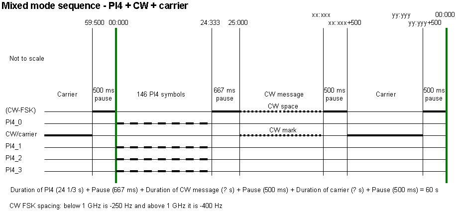
A neat mixed mode PI4 + CW + carrier sequence is as show in the table below.
Table 2. Mixed mode PI4 + CW + carrier sequence flow.
| Start SS,Th |
Message |
| 00,000 | MGM |
| 24,333 | Pause (no signal) |
| 25,000 | CW callsign and locator |
| XX,YY | Pause (no signal) |
| XX,YY+0,5 | Carrier |
| 59,500 | Pause (no signal) |
The MGM ends at ~24,333 a pause is then added making the overall 25 s length. The pause ~667 ms. The other pauses are 500 ms.
The duration of the CW ID is based upon the length of the callsign and locator in morse code and speed at 60 LPM/12 WPM. The carrier ends at 59,50. The combined length of the CW ID, pause carrier and pause is 35 s.
| MGM | P | CW ID | P | Carrier | P |
Where P are the pauses.
Fig. 2. The standard PI4 + CW + carrier sequence including CW FSK.
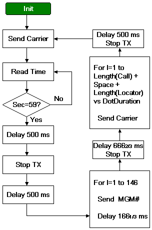
The below pseudo source code can be translated into your favourite programming language. The example has only one MGM message but it can send either CW on-off or FSK CW.
Fig 3. Flow chart for a one minute PI4, CW ID (callsign and locator) and carrier.
Constants
  Call="Callsign"
  Locator="Locator"
  DotDuration=100                                          // 100 ms is equivalent to 12 WPM/60 LPM
  MGM_NbrBits=146
  Carrier="FTW0"
  MGM_Carriers array 0 to 3 of MGM_Carriers0=Carrier, MGM_Carriers1="FTW1", MGM_Carriers2="FTW2", MGM_Carriers3="FTW3"
  MGM_Tones array 1 to MGM_NbrBits                         // Array with carrier number 0 to 3

Procedure NoTX                                             // Implementation depends on actual hardware
begin
  Send no TX code to "device"
end

Procedure TX(Value)                                        // Implementation depends on actual hardware
begin
  Send frequency instruction word to "device"
  Send frequency Value FTW to "device"
end

Function WaitUntil59Second:byte                            // Waits until the 59 second is reached
begin                                                      // $GPRMC,HHMMSS,A...*CC
  Loop
    Receive serial NMEA data from GPS
  until Frame='$GPRMC' and SS='59'
end

Procedure SendMorse(Morse)
begin
  MorsePattern=Morse and 11111000                          // Bit7 to Bit3 of Morse[I]
  MorseLength=Morse and 00000111                           // Bit2 to Bit0 of Morse[I]

  For I=1 to MorseLength
  begin
    TX(Carrier)
    If Bit 8-I of MorsePattern=1                           // 0 = dot, 1 = dash
      Delay 3 * DotDuration
    else
      Delay DotDuration

    NoTX

    Delay DotDuration                                      // Space between dots and dashes in same character
  end
  Delay 2 * DotDuration                                    // Space between two Morse characters (1 DotDuration has already passed)
end

Procedure Initialize                                       // Implementation depends on actual hardware
begin
  Config "device"
  NoTX                                                     // Do not send anything while initializing hardware

  Config NMEA serial input
end

BEGIN
  Initialize

  Loop
  begin
    TX(Carrier)
    WaitUntil59Second                                      // Wait until the 59th sec
    Delay 500 ms                                           // May need to be adjusted to specific H/W and clock

    NoTX
    Delay 500 ms                                           // May need to be adjusted to specific H/W and clock

    For I=1 to MGM_NbrBits                                 // Send PI4, must start at 0 sec
    begin
      TX(MGM_Carriers[MGM_Tones[I]])                       // Send relevant MGM carrier
      Delay 166,667 ms minus for loop processing time      // Replace simple delay with interrupt in a real application
    end

    NoTX
    Delay 666,667 ms                                       // May need to be adjusted to specific H/W and clock so that CW starts at the 25th s

    For I=1 to Length(Call)                                // Send call
      SendMorse(Call[I])

    Delay 500 ms - 3 * DotDuration                         // May need to be adjusted to specific H/W and clock (3 DotDuration have already passed)

    For I=1 to Length(Locator)                             // Send locator
      SendMorse(Locator[I])

    Delay 500 ms - 3 * DotDuration                         // May need to be adjusted to specific H/W and clock (3 DotDuration have already passed)
  end
END
And: binary and operation bit to bit between two variables
Morse character encoded byte: "A" = 01 010 = 1 dot 1 dash and has a length of 010 = 2 bits, "B" = 1000 100, "C" = 1010 100 ... "/" = 10010101 where is "don't care" i.e. either 0 or 1
Sound (MP3) sample sequence of PI4, CW ID and carrier (1 MB).
Collection of PI-RX recordings (WAV) of PI4, CW ID and carrier (36 MB).
Video (MP4) sample sequence of PI4, CW ID and carrier (18 MB).
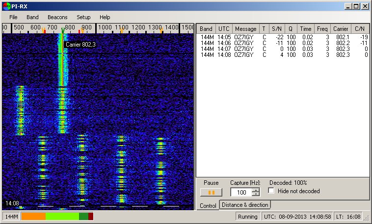
Example of PI4 decoding using PI-RX.
Christo, LZ2HV, has implemented a PI4 decoder in his MSHV program that runs on both Linux and Windows.
Please contact Bo, OZ2M, at my callsign @ this domain.
Bo, OZ2M, www.rudius.net/oz2m