2021-12-31
![]()
As a spin off from the Next Generation Beacons project a generic PI4 + CW + carrier beacon controller has been developed for the Arduino platform hence its name PI4ino. This means that you can use your favorite radio frequency device while using the generic controller to generate the PI4 + CW + carrier sequence. This can be one of the already integrated devices or a new device which you may integrate yourself from scratch or by modifying one of the other device support files.
Thanks to José, EA3HMJ, for providing the ADF4350/ADF4351 files, to Waldek, SP2ONG, for the radio idea with the audio soft-DDS and to Steen, OZ2TG, for helping out with the LMX2541 integration. Thanks to Brian, GM8BJF and Bernie, GM4WZG, for correcting the loading of the ADF5355 and ADF5356 registers.
In case you are looking for how to generate a frequency using one of the above devices you may even use the .cpp files to understand how a frequency is made without using a library with a lot of overhead.
But before you decide to put a beacon on the air you should ask yourself if there is a need for one more beacon? Are there other beacons on the same band within normal reach? If so your beacon may not be needed unless it brings something new to the airwaves - a PI4 + CW + carrier beacon may do just that. However, don't forget to ask for a coordinated frequency for your beacon either with your national or regional IARU beacon coordinators prior to putting your beacon on the air.
You can also take a look at the RFzero GPS controlled RF source.
You should not compare the simple PI4ino generic beacon controller with the the Next Generation Beacons platform. The latter is an ultra high performance platform offering super low phase noise, frequency and time precision, configuration flexibility and a multitude of sequences and MGMs, but also in a different price range. However, PI4ino can help you putting a mixed mode PI4 + CW + carrier beacon on the air with relaxed performance but also at a lower cost or for evaluation purposes before doing it right.
The PI4ino S/W has been written with simplicity and ease of reading in mind. Thus, some more advanced features have deliberately been omitted.
The relevant hardware consist of the following units:
In addition to the above units you will also need a power supply and some proper filtering and a power amplifier if you want to increase the output power of the frequency device.
How you implement your frequency device is entirely up to you, e.g. you can use a DDS clocked by an on-board oscillator, a GPSDO controlled clock or a synthesizer. It is your choice. But you must connect the relevant pins of the frequency device to the Arduino.
| SPECTRUM WARNING The dirt cheap AD9850 and AD9851 boards you can find on eBay have a really lousy output spectrum that a low pass filter will not clean up! Way to many people focus only on the harmonics. But the close-in spectrum, phase noise and spurious performances are often neglected and they may pose far greater problems than the harmonics of the fundamental frequency do. Square wave generators/clock circuits like the Si570 and Si5351A are not spurious free either. Furthermore are design considerations important when it comes to loop filters, analog and digital power supply partitioning, low noise power supply regulators and PCB track layout. Quality costs money and design time. So before you put a signal on the air please investigate the spectrum performance of your circuit in details. Your fellow radio amateurs should also be able to use the spectrum and not just you. |
The PI4ino uses the NMEA $GPRMC frame. Alternatively you will have to modify the NMEA command parser to match another data frame.
When the controller detects a valid GPS signal, in the $GPRMC string during the carrier period, the green LED will be lit otherwise it will be off.
If your satellite position device is not a GPS receiver but receiving from one of the other systems you may have to modify the S/W for the alternative $GPRMC string e.g. $GNRMC.
In case a GPS receiver is not connected or the data from it is corrupted the PI4 part of the sequence is omitted and an unsynchronized CW ID and a fixed carrier length of 20 s are transmitted.
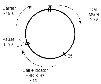
The sequence begins at the full minute, mm:00:000, with PI4 (call sign or message) for the next 24,333 s, mm:24:333. Then a short pause of 667 ms, mm:25:000, followed by CW ID (call sign and locator), followed by a 500 ms pause, then carrier until 59,5 s, mm:59:500, and a 500 ms, mm+1:00:00, pause until the next cycle begins. During the pauses the -FSK (space) frequency will be generated, i.e. carrier offset of -250 Hz below 1 GHz and -400 Hz above 1 GHz.
During the PI4 part of the sequence the "TX modulation" LED will flash at half the PI4 rate, i.e. 3 Hz, during the CW it will follow the mark and during the carrier period it will be lit continuously.
You can probably use most of the Arduinos available, however, the PI4ino has been tested on the following Arduino devices:
You can use an Arduino Mega too, but, there is not really any need for it. So save your money for a better frequency device. Also verify that the SPI/I2C, if needed by the frequency device, is implemented in the Arduino IDE for alternative devices. Otherwise you will have to develop a bit banging solution yourself.
You can also take a look at the RFzero GPS controlled RF source for.
Besides the necessary voltage supplies and ground connections the below table shows the connections to the Arduino, frequency device, GPS and status LEDs. If you are using a GPS with 3,3 V communication you may use the 3,3 V from the Arduino. But be aware that you will need a 3,3 V to/from 5 V level converter also for the communication lines (TX and RX). Similarly, level converters may be needed between the Arduino and the frequency device. As long as the direction is from 5 V to 3,3 V a resistor, e.g. 470 Ω, and a 3,3 V zener diode may be used on each line.
| Arduino pin* | Usage |
| 0 | RX data from USB |
| 1 | TX data to USB |
| 6 | RX data from the GPS (connect to TX on the GPS) |
| 7 | TX data to the GPS (connect to RX on the GPS), may not be needed but it depends on the GPS receiver |
| 8 | Frequency device reset, if needed/implemented on the frequency device |
| 9 | Frequency device update, if needed/implemented on the frequency device |
| 10 | SPI Slave Select (SS), if needed. Often this pin on the frequency device is connected to ground/high in the design/radio PTT |
| 11 | SPI Master Out Slave In (MOSI)/Audio soft DDS output to radio |
| 12 | Reserved for SPI Master In Slave Out (MISO). Currently not implemented in the S/W as there is no use for it |
| 13 | SPI Serial Clock (SCK) |
| A0 | GPS valid LED via 680 Ω resistor. A green LED is suggested |
| A1 | Reserved for frequency device lock detect via 680 Ω resistor, optional. A yellow LED is suggested |
| A2 | "TX modulation" via 680 Ω resistor. Flashes with half PI4 rate and 1:1 during CW and carrier. A red LED is suggested |
| A4 | I2C SDA to the frequency device |
| A5 | I2C SCL to the frequency device |
*: Sometimes the Arduino H/W names the digital pins D#. But it should make no difference.
The frequency device determines whether you use the SPI or I2C bus pins.
Communication to and from the GPS is made with the SoftwareSerial Arduino library. Doing so allows the USB port to be used for normal Arduino programming. If using an Arduino with more than one H/W serial port, e.g. Arduino Mega, the SoftwareSerial library should be replaced with the normal Serial communication library. In case of using the Arduino as an audio generator the SoftwareSerial interrupts the audio signal during the plain carrier period. Either this is an acceptable trade off or you will have to use the normal Serial library instead or an Arduino, e.g. Mega, with more than one hardware serial channel. However, if you decide to use the normal Serial library on serial channel 0 you may not be able to load the software without disconnecting the GPS receiver.
The remainder of the pins are unused and may be used for additional functionality that you can create yourself.
Connect the AD9833 in the following way for serial loading.
| Arduino pin | AD9833 pin | AD9833 Mnemonic | Functionality |
| 9 | 8 | FQ_UD | Frequency device update |
| 11 | 25 | SDATA | SPI Master Out Slave In (MOSI) |
| 13 | 7 | SCLK | SPI Serial Clock (SCK) |
Arduino pin 8 and pin 10 are not used.
Connect the AD9850 in the following way for serial loading.
| Arduino pin | AD9850 pin | AD9850 Mnemonic | Functionality |
| 8 | 22 | RESET | Frequency device reset |
| 9 | 8 | FQ_UD | Frequency device update |
| 11 | 25 | D7 | SPI Master Out Slave In (MOSI) |
| 13 | 7 | W_CLK | SPI Serial Clock (SCK) |
Arduino pin 10 is not used.
Connect the AD9851 in the following way for serial loading.
| Arduino pin | AD9851 pin | AD9851 Mnemonic | Functionality |
| 8 | 22 | RESET | Frequency device reset |
| 9 | 8 | FQ_UD | Frequency device update |
| 11 | 25 | D7 | SPI Master Out Slave In (MOSI) |
| 13 | 7 | W_CLK | SPI Serial Clock (SCK) |
Arduino pin 10 is not used.
Connect the AD9912 in the following way.
| Arduino pin | AD9912 pin | AD9912 Mnemonic | Functionality |
| 8 | 59 | RESET | Frequency device reset |
| 9 | 60 | IO_UPDATE | Frequency device update |
| 10 | 61 | CSB | SPI Slave Select (SS), if needed |
| 11 | 63 | SDIO | SPI Master Out Slave In (MOSI) |
| 13 | 64 | SCLK | SPI Serial Clock (SCK) |
Most Arduinos run on 5 V so you will need a 5 V to/from 3,3 V level converter.
Connect the AD9913 in the following way.
| Arduino pin | AD9913 pin | AD9913 Mnemonic | Functionality |
| 8 | 25 | MASTER_RESET | Frequency device reset |
| 9 | 27 | IO_UPDATE | Frequency device update |
| 10 | 28 | CS | SPI Slave Select (SS), if needed |
| 11 | 29 | SDIO | SPI Master Out Slave In (MOSI) |
| 13 | 30 | SCLK | SPI Serial Clock (SCK) |
Most Arduinos run on 5 V so you will need a 5 V to/from 1,8 V level converter.
Connect the ADF4350/ADF4351 in the following way.
| Arduino pin | ADF4350/~1 pin | ADF4350/~1 Mnemonic | Functionality |
| 9 | 3 | LE | Frequency device update |
| 11 | 2 | DATA | SPI Master Out Slave In (MOSI) |
| 13 | 1 | CLK | SPI Serial Clock (SCK) |
Arduino pin 8 is not used.
Most Arduinos run on 5 V so you will need a 5 V to/from 3,3 V level converter.
It is possible to modify/speed up changing frequency if some registers are identical. Reloading of identical contents, typically found in registers 2-5, is superfluous. If so, you will have to modify the SetFrequency function slightly yourself. But don't forget to load all registers at least ones. This can be done in the Initialize function. Also loading all registers can cause clicks because of PLL recalibration. Thus you may have to experiment a bit.
Here is a YouTube video made by José, EA3HMJ.
Connect the ADF5355 in the following way.
| Arduino pin | ADF5355 pin | ADF5355 Mnemonic | Functionality |
| 9 | 3 | LE | Frequency device update |
| 11 | 2 | DATA | SPI Master Out Slave In (MOSI) |
| 13 | 1 | CLK | SPI Serial Clock (SCK) |
Arduino pin 8 is not used.
Most Arduinos run on 5 V so you will need a 5 V to/from 1,8 V level converter.
It is possible to modify/speed up changing frequency if some registers are identical. Reloading of identical contents, typically found in registers 3-12, is superfluous. If so, you will have to modify the SetFrequency function slightly yourself. But don't forget to load all registers at least ones. This can be done in the Initialize function. Also loading all registers can cause clicks because of PLL recalibration. Thus you may have to experiment a bit.
Connect the ADF5356 in the following way.
| Arduino pin | ADF5356 pin | ADF5356 Mnemonic | Functionality |
| 9 | 3 | LE | Frequency device update |
| 11 | 2 | DATA | SPI Master Out Slave In (MOSI) |
| 13 | 1 | CLK | SPI Serial Clock (SCK) |
Arduino pin 8 is not used.
Most Arduinos run on 5 V so you will need a 5 V to/from 1,8 V level converter.
It is possible to modify/speed up changing frequency if some registers are identical. Reloading of identical contents, typically found in registers 3-13, is superfluous. If so, you will have to modify the SetFrequency function slightly yourself. But don't forget to load all registers at least ones. This can be done in the Initialize function. Also loading all registers can cause clicks because of PLL recalibration. Thus you may have to experiment a bit.
Connect the LMX2541 in the following way.
| Arduino pin | LMX2541 pin | LMX2541 Mnemonic | Functionality |
| 9 | 34 | LE | Frequency device update |
| 11 | 32 | DATA | SPI Master Out Slave In (MOSI) |
| 13 | 33 | CLK | SPI Serial Clock (SCK) |
Arduino pin 8 is not used.
Most Arduinos run on 5 V so you will need a 5 V to/from 3,3 V level converter.
It is possible to modify/speed up changing frequency if some registers are identical. Reloading of identical contents, typically found in some registers, is superfluous. If so, you will have to modify the SetFrequency function slightly yourself. But don't forget to load all registers at least ones. This can be done in the Initialize function. Also loading all registers can cause clicks because of PLL recalibration initiated by loading register 0/index 11. Thus you may have to experiment a bit.
Connect to the audio signal in the following way.
| Arduino pin | Radio | Functionality |
| 10 | PTT pin | PTT signal to radio |
| 11 | Signal pin | Audio signal to radio |
Timer2 is used so the output pin can only be 11, or 3 by altering the S/W, on the Arduino Nano/Uno. Other Arduinos may provide other options.
Please note that the output frequencies are offset by +1 kHz. This is done to avoid the second harmonics fall inside the used spectrum.
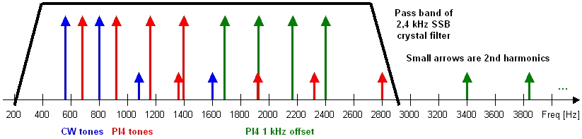
By offsetting +1 kHz the second harmonics will fall outside the audio pass band and will be attenuated by the crystal filter in the radio. However, this also means that the radio will have to be offset -1 kHz for the different frequencies to be correctly located.
Unplug IC2, PIC16F628, and connect the RDDS unit in the following way to the pins in the empty IC2 socket.
| Arduino pin | IC2 pin | IC2 Mnemonic | AD9851 pin | AD9851 Mnemonic | Functionality |
| 8 | 2 | RA3 | 22 | RESET | Frequency device reset, if needed |
| 9 | 18 | RA1 | 8 | FQ_UD | Frequency device update |
| 11 | 17 | RA0 | 25 | D7 | SPI Master Out Slave In (MOSI) |
| 13 | 1 | RA2 | 7 | W_CLK | SPI Serial Clock (SCK) |
Arduino pin 10 is not used.
Connect the Si5351A in the following way.
| Arduino pin | Si5351A pin | Si5351A Mnemonic | Functionality |
| A4 | 5 | SDA | I2C SDA to the frequency device |
| A5 | 4 | SCL | I2C SCL to the frequency device |
Output is on CLK0.
Most Arduinos run on 5 V so you will need a 5 V to/from 3,3 V level converter.
Connect the Si570 in the following way.
| Arduino pin | Si570 pin | Si570 Mnemonic | Functionality |
| A4 | 7 | SDA | I2C SDA to the frequency device |
| A5 | 8 | SCL | I2C SCL to the frequency device |
Most Arduinos run on 5 V so you will need a 5 V to/from 3,3 V level converter.
Connect the GPS in the following way.
| Arduino pin | GPS | Functionality |
| 6 | TXD | Data from the GPS to the Arduino |
| 7 | RXD | Data to the GPS from the Arduino, may not be needed but depends on the GPS receiver |
The communication speed should be 9600 Baud and 8N1. If another speed is needed it is necessary to change the settings in the S/W.
It may also be relevant to configure the GPS before usage as the S/W expects only the $GPRMC frame to be sent every second and no other frames at all.
The software is released under GNU and copyright José, EA3HMJ (ADF4350/ADF4351) and Bo, OZ2M. A spreadsheet is provided together with the source code for calculating the relevant frequency tuning words for some of the devices. For the ADF4350/ADF4351, ADF5355 and ADF5356 please consult the Analog Devices software tools. For the LMX2541 please consult Texas Instrument's CodeLoader software.
If you integrate a new device feel free to write me and I will be happy to include your files too.
If you are unfamiliar with the world of Arduino you should download and install the Arduino IDE first. The PI4ino S/W is fairly basic which makes it easier to study and modify if needed.
In the PI4ino.ino file you must edit the section marked "// *** Beacon and hardware configuration ***" to match your needs.
| Parameter | Description |
| char pi4Message[9] = "OZ2M "; | The PI4 message. Must be 8 characters, left justified and padded with spaces if needed |
| char callsign[] = "OZ2M"; | The CW callsign. Only A-Z, 0-9 and / |
| char locator[] = "JO65FR"; | The CW locator. Only A-X and 0-9 |
| const int gpsBaudRate = 9600; | The GPS NMEA Baud rate |
| const int gpsDataDelay = 200; | The GPS data frame delay in ms vs. real time Please note that some GPS receivers are more than 1 s off. Some even more than 2 s |
The deviceReset, deviceUpdate, spiSCK, spiSS, i2cSDA, i2cSCL and audioSignal pins must not be changed for an Arduino Nano and Arduino Uno. However, it may be relevant for other Arduino boards.
Then disable all the irrelevant frequency devices and enable the relevant one. Do this by adding and removing the relevant /* */.
In the relevant "device name".cpp file you must change the frequency tuning/register words to match your needs. The PI4ino.xls spreadsheet can be used to calculate the frequency words for some of the devices. But for the ADF4350, ADF4351, ADF5355, ADF5356 and LMX2541 you will have to use the tools provided by the manufacturers.
In the GPSInit() function you can insert strings that are needed to configure the GPS prior to usage. Only the NMEA $GPRMC string must be sent by the GPS and it must only be sent ones per second, not more not less.
Click to download the PI4ino software and the other files. Unzip and copy all files to a directory named PI4ino.
If the frequency device is not a Si570 the Si570_Regs.ino file must be renamed, deleted or located in a different directory.
| Version | Description |
| 1.7.1 2018-08-31 |
Bug
|
| 1.7.0 2017-09-22 |
Changes
|
| 1.6.1 2017-09-03 |
Bugs
|
| 1.6.0 2017-08-19 |
New
|
| 1.5.0 2016-02-21 |
New
|
| 1.4.1 2016-01-10 |
Bugs
|
| 1.4.0 2016-01-08 |
New
|
| 1.3.0 2015-12-27 |
New
|
| 1.2.1 2015-12-19 |
Bugs
|
| 1.2.0 2015-05-02 |
New
Bugs
|
| 1.1.0 2014-12-30 |
New
Changes
Bugs
|
| 1.0.0 2014-12-27 |
First release |
Bo, OZ2M, www.rudius.net/oz2m