2014-01-11
| Overview | VCO-PLL | DDS | GPS reference | Distribution amplifiers | Service management | Sequence | PI4 | Software |
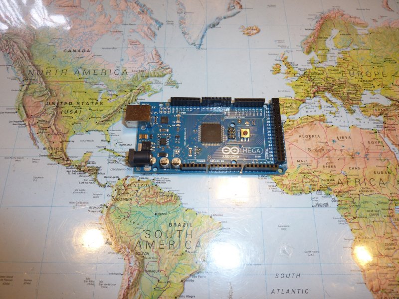
Arduino Mega board used for service management.
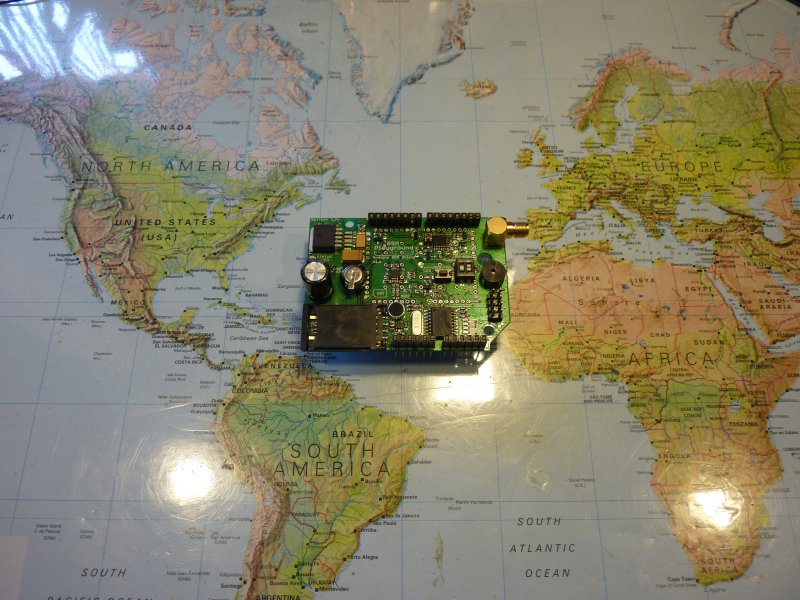
Arduino GSM shield board used for service management.
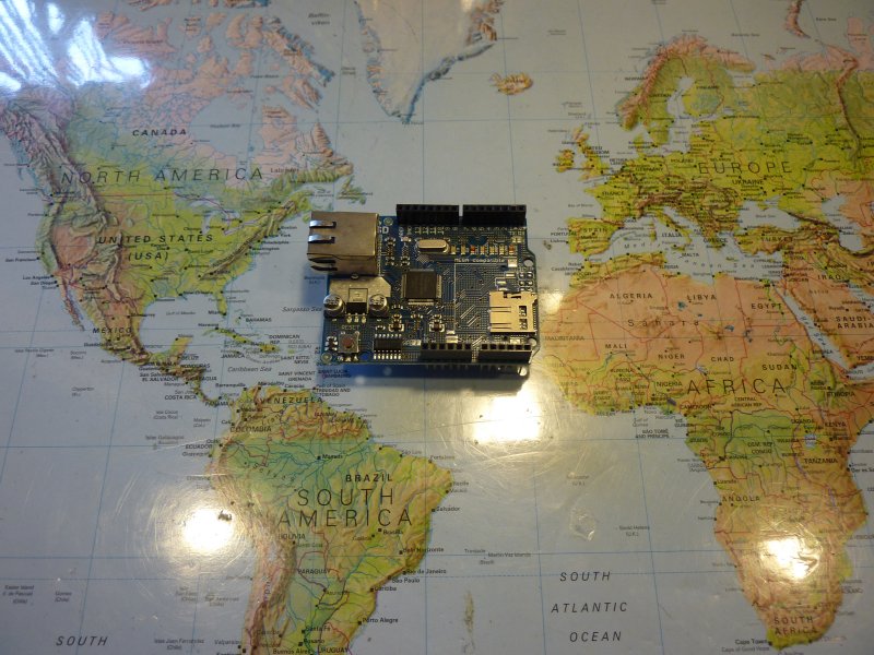
Arduino Ethernet shield board used for service management.
The service management overlay of the Next Generation Beacons platform is based upon the Arduino world. It is an open source-open hardware platform offering both hardware and software that is easy to learn and use. The best of all is that there are many users world wide that have made a lot of libraries and solutions that more or less resembles the ones used for monitoring and servicing the Next Generation Beacons platform.
Another important advantage about the Arduino is that there are hardware extensions (shields) available for almost any thinkable need. In case of a beacon located away from home SMS or email notification are obvious choices in case of malfunctioning. Another possibility is remote configuration of the Next Generation Beacons platform or even a status page found on the web.
By using an open and rich platform it is easy to tailor it to the specific beacon site and the power supplie(s), amplifier(s), directional coupler(s). No two beacon sites are identical. Thus a lot of local adaptation is relevant.
In principle you can run the Next Generation Beacons platform without any service management overlay. All configuration can be down with a PC either at the beacon site or at home before going to the beacon. If you already have a monitoring solution is may be all what you need. But for OZ7IGY we have chosen to install a service management overlay based upon the Arduino world. This page is meant as inspiration as every beacon site is unique.
In case of the OZ7IGY service management overlay the following Arduino parts are used:
Arduino Ethernet SD shield (only for development/academic use as there is no Ethernet access at the OZ7IGY site)
Currently we have not developed any service management overlay to OZ7IGY but will as the site will be populated with the Next Generation Beacons.
The Arduino Mega 2560 is a microcontroller board based on the ATmega2560 (datasheet). It has 54 digital input/output pins (of which 14 can be used as PWM outputs), 16 analog inputs, 4 UARTs (hardware serial ports), a 16 MHz crystal oscillator, a USB connection, a power jack, an ICSP header, and a reset button. It contains everything needed to support the microcontroller; simply connect it to a computer with a USB cable or power it with a AC-to-DC adapter or battery to get started.
| Microcontroller | ATmega2560 |
| Operating Voltage | 5 V |
| Input Voltage (recommended) | 7-12 V |
| Input Voltage (limits) | 6-20 V |
| Digital I/O Pins | 54 (of which 14 provide PWM output) |
| Analog Input Pins | 16 |
| DC Current per I/O Pin | 40 mA |
| DC Current for 3.3V Pin | 50 mA |
| Flash Memory | 256 kB of which 8 kB used by bootloader |
| SRAM | 8 kB |
| EEPROM | 4 kB |
| Clock Speed | 16 MHz |
The Arduino Mega can be powered via the USB connection or with an external power supply. The power source is selected automatically.
External (non-USB) power can come either from an AC-to-DC adapter (wall-wart) or battery. The adapter can be connected by plugging a 2.1 mm center-positive plug into the board's power jack. Leads from a battery can be inserted in the Gnd and Vin pin headers of the POWER connector.
The board can operate on an external supply of 6 to 20 V. If supplied with less than 7 V, however, the 5 V pin may supply less than five volts and the board may be unstable. If using more than 12V, the voltage regulator may overheat and damage the board. The recommended range is 7 to 12 V.
The Mega2560 differs from all preceding boards in that it does not use the FTDI USB-to-serial driver chip. Instead, it features the Atmega8U2 programmed as a USB-to-serial converter.
The power pins are as follows:
The ATmega2560 has 256 kB of flash memory for storing code (of which 8 KB is used for the bootloader), 8 KB of SRAM and 4 KB of EEPROM (which can be read and written with the EEPROM library).
Each of the 54 digital pins on the Mega can be used as an input or output, using pinMode(), digitalWrite(), and digitalRead() functions. They operate at 5 volts. Each pin can provide or receive a maximum of 40 mA and has an internal pull-up resistor (disconnected by default) of 20-50 kOhms. In addition, some pins have specialized functions:
The Mega2560 has 16 analog inputs, each of which provide 10 bits of resolution (i.e. 1024 different values). By default they measure from ground to 5 volts, though is it possible to change the upper end of their range using the AREF pin and analogReference() function.
There are a couple of other pins on the board:
The Arduino Mega2560 has a number of facilities for communicating with a computer, another Arduino, or other microcontrollers. The ATmega2560 provides four hardware UARTs for TTL (5 V) serial communication. An ATmega8U2 on the board channels one of these over USB and provides a virtual com port to software on the computer (Windows machines will need a .inf file, but OSX and Linux machines will recognize the board as a COM port automatically. The Arduino software includes a serial monitor which allows simple textual data to be sent to and from the board. The RX and TX LEDs on the board will flash when data is being transmitted via the ATmega8U2 chip and USB connection to the computer (but not for serial communication on pins 0 and 1).
A SoftwareSerial library allows for serial communication on any of the Mega2560's digital pins.
The ATmega2560 also supports I2C (TWI) and SPI communication. The Arduino software includes a Wire library to simplify use of the I2C bus; see the documentation on the Wiring website for details. For SPI communication, use the SPI library.
The Arduino Mega can be programmed with the Arduino software (download). For details, see the reference and tutorials.
The ATmega2560 on the Arduino Mega comes preburned with a bootloader that allows you to upload new code to it without the use of an external hardware programmer. It communicates using the original STK500 protocol (reference, C header files).
You can also bypass the bootloader and program the microcontroller through the ICSP (In-Circuit Serial Programming) header; see these instructions for details.
The ATmega8U2 firmware source code is available in the Arduino repository. The ATmega8U2 is loaded with a DFU bootloader, which can be activated by connecting the solder jumper on the back of the board (near the map of Italy) and then resetting the 8U2. You can then use Atmel's FLIP software (Windows) or the DFU programmer (Mac OS X and Linux) to load a new firmware. Or you can use the ISP header with an external programmer (overwriting the DFU bootloader). See this user-contributed tutorial for more information.
Rather then requiring a physical press of the reset button before an upload, the Arduino Mega2560 is designed in a way that allows it to be reset by software running on a connected computer. One of the hardware flow control lines (DTR) of the ATmega8U2 is connected to the reset line of the ATmega2560 via a 100 nF capacitor. When this line is asserted (taken low), the reset line drops long enough to reset the chip. The Arduino software uses this capability to allow you to upload code by simply pressing the upload button in the Arduino environment. This means that the bootloader can have a shorter timeout, as the lowering of DTR can be well-coordinated with the start of the upload.
This setup has other implications. When the Mega2560 is connected to either a computer running Mac OS X or Linux, it resets each time a connection is made to it from software (via USB). For the following half-second or so, the bootloader is running on the Mega2560. While it is programmed to ignore malformed data (i.e. anything besides an upload of new code), it will intercept the first few bytes of data sent to the board after a connection is opened. If a sketch running on the board receives one-time configuration or other data when it first starts, make sure that the software with which it communicates waits a second after opening the connection and before sending this data.
The Mega2560 contains a trace that can be cut to disable the auto-reset. The pads on either side of the trace can be soldered together to re-enable it. It's labeled "RESET-EN". You may also be able to disable the auto-reset by connecting a 110 ohm resistor from 5 V to the reset line; see this forum thread for details.
The Arduino Mega2560 has a resettable polyfuse that protects your computer's USB ports from shorts and overcurrent. Although most computers provide their own internal protection, the fuse provides an extra layer of protection. If more than 500 mA is applied to the USB port, the fuse will automatically break the connection until the short or overload is removed.
Embedded GSM/GPRS Module GE-863 QUAD features a Quad-Band GPRS Class 10 (GSM 850, 900, DCS 1800, PCS1900 MHz) as well as extended temperature range and RF Sensitivity. The module is equipped with the chipset V3 (firmware 6.04.104).
Power supply for GSM Module is able to handle high ripple current (2 A) when the GSM Module is active. It is designed with Micrel MIC29302. The Shield is powered from an Arduino board so it can be powered either directly from USB or from an adaptor through Arduino board. The setting of supply path is automatic. A large capacitor is used for voltage filtration so that you can easily supply the board directly from USB (guaranteed for calls and CSD data). We recommend to use an AC-DC adaptor or LiPol battery for GPRS connection.
Connector for 3,7 V LiPol battery and Charging circuit – it is possible to connect 3,7 V LiPol battery so that it can be used for supplying power to the GSM Module and also to the Arduino board. The battery is charged during normal operation of the GSM Shield from USB or adaptor with a current of 200mA. Battery operation can be selected from a switch. This feature is also helpful if the computer is not able to deliver the current required by the GSM module (during class 10 GPRS connection). It is recommended to use 3,7 V LiPol battery with capacity from 500 mAh to 1000 mAh with a JST connector. An appropriate battery is 1000 mAh LiPol battery or 860 mAh LiPol battery.
Electret Microphone – the mike feature is based on a sensitive electret microphone that offers together with other circuits and particular PCB layout the clear sound. Even the GSM noise is quite aggressive but there is no typical GSM noise in the microphone path at all.
Embedded DTMF Receiver – this feature allows controlling of any other function of GSM Playground using of an ordinary phone. DTMF circuit (based on Holtek HT9170) is able to recognize up to 16 different signals (buttons on your mobile phone) and transfer this information to Arduino board for other evaluation. It is possible to control just a relay but also increase a volume of loudspeaker or mute the microphone using this feature.
ON/OFF Button – there is a button for turning ON and OFF of the module. It is possible to do the same directly from the Arduino board. The reset signal of the GSM module is connected to the Arduino. This feature can help to improve a reliability of the whole application.
Enhanced serial communication – this feature can help you to develop your Arduino application faster and better. There is a switch for controlling of the way of serial communication. In the first position you can communicate from PC terminal software directly to the GSM Module. This is very useful for trying and learning of the GSM Module AT commands. The second position switches to communication between Arduino - PC and Arduino - GSM Module. In this position the Arduino board can communicate with PC application as we are used to but also with the GSM module. Important! There is no need to remove ATMEGA microcontroller if the board is used as a GSM gateway (communication PC - GSM Module).
Back up capacitor for time and alarm features – the adjustment of time can be quite annoying so there is a back up capacitor 0,22 F on the PCB. It is able to backup Real Time Clock embedded in the GSM Module for minimally 24 hours. The GSM Module offers also Alarm related functions – Alarm signal can wake up an Arduino board in desired time by a reset, then the board can do something (send SMS) and go sleep again...
Temperature Sensor – built in temperature sensor LM61BIM3 allows measuring of the temperature from -25 °C to +85 °C with accuracy ±2.0 °C at 25 °C. The LM61's output voltage is linearly proportional to Celsius (Centigrade) temperature (+10 mV/°C) and it makes it very easy to use.
User Button and User LED – this simple user interface can be used for different purpose (e.g. make a call, send a SMS, indicate a call...).
User Connector – this connector offers 4 digital inputs or outputs and several supplying voltages so it can be easily used to make your application more versatile.
Standard SMA Connector for GSM antenna – there is a right angle SMA female connector soldered on the PCB so the connection of antenna can be very simple. This Quad-band Antenna is suitable because it is pretty small.
Embedded SIM card holder – the quality SIM card holder equipped with the contact for safe removing of SIM card is soldered directly on the Shield PCB.
Stackable feature – GSM Playground accepts prototype shields or other boards with Arduino compatible interface. The GSM Shield uses digital pins 0 to 9 but the pins 6, 7, 8 and 9 can be also used for other purpose (they can be switched to high impedance). The GSM Playground is compatible with Arduino Ethernet Shield.
PCB Layout is made with a special care of well grounding and noises elimination even though it is still only cheap two layer PCB.
The Arduino Ethernet Shield allows an Arduino board to connect to the internet. It is based on the Wiznet W5100 ethernet chip (datasheet). The Wiznet W5100 provides a network (IP) stack capable of both TCP and UDP. It supports up to four simultaneous socket connections. Use the Ethernet library to write sketches which connect to the internet using the shield. The ethernet shield connects to an Arduino board using long wire-wrap headers which extend through the shield. This keeps the pin layout intact and allows another shield to be stacked on top.
The shield contains a micro-SD card slot, which can be used to store files for serving over the network. It is compatible with the Arduino Uno, Mega, and previous models. The SD card can be accessed using the SD library.
The shield also includes a reset controller, to ensure that the W5100 Ethernet module is properly reset on power-up.
Arduino communicates with both the W5100 and SD card using the SPI bus (through the ICSP header). This is on digital pins 11, 12, and 13 on the Duemilanove and pins 50, 51, and 52 on the Mega. On both boards, pin 10 is used to select the W5100 and pin 4 for the SD card. These pins cannot be used for general i/o. On the Mega, the hardware SS pin, 53, is not used to select either the W5100 or the SD card, but it must be kept as an output or the SPI interface won't work.
Note that because the W5100 and SD card share the SPI bus, only one can be active at a time. If you are using both peripherals in your program, this should be taken care of by the corresponding libraries. If you're not using one of the peripherals in your program, however, you'll need to explicitly deselect it. To do this with the SD card, set pin 4 as an output and write a high to it. For the W5100, set digital pin 10 as a high output.
The shield provides a standard RJ45 ethernet jack.
The reset button on the shield resets both the W5100 and the Arduino board.
The shield contains a number of informational LEDs:
The solder jumper marked "INT" can be connected to allow the Arduino board to receive interrupt-driven notification of events from the W5100, but this is not supported by the Ethernet library. The jumper connects the INT pin of the W5100 to digital pin 2 of the Arduino.
Please contact Bo, OZ2M, at my callsign @ this domain.
Bo, OZ2M, www.rudius.net/oz2m