2018-10-16
| Overview | VCO-PLL | DDS | GPS reference | Distribution amplifiers | Service management | Sequence | PI4 | Software |
The world's oldest beacon · OZ7IGY in JO55WM · 28 MHz to 24 GHz.

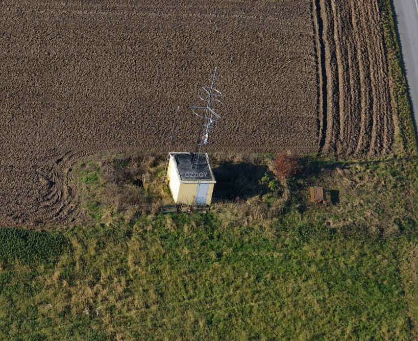
OZ7IGY goes all the way back to the International Geophysical Year in 1957. From its start on 144 MHz it has ever since been on air continuously and on ever more and more bands. Today OZ7IGY transmits on 28 MHz, 40 MHz, 50 MHz, 70 MHz, 144 MHz, 432 MHz, 1,3 GHz, 2,3 GHz, 3,4 GHz, 5,7 GHz, 10 GHz and 24 GHz. Most of the HF, VHF and UHF technology used by OZ7IGY is old(er) land mobile equipment modified for the purpose. For the microwave bands most of the technology is dedicated radio amateur beacon designs while power amplifiers are often surplus. However, given the latest developments in digital modulation techniques and RF-circuits it is time also for OZ7IGY to take advantage of these technologies. This is what the Next Generation Beacons project is all about. Not only for OZ7IGY's use but the platform is open for others and the software can easily be adapted to other modulations and sequences such as the International Beacon Project, WSPR, JT4 ...
Short video showing OZ7IGY and the surroundings.
The Next Generation Beacons platform for the OZ7IGY beacons encompasses both analog and digital modes, i.e. CW FSK and MGM in a mixed mode configuration. The advantage of the mixed mode is that humans can decode the CW FSK by ear and the MGM can be decoded by computers way below what is audible. Therefore the MGM can be used for “pre-human-conditions” or early warning monitoring.
Before deciding what to design it is worthwhile to find out what is needed. The usage perspective is the right way to identify the requirements.
The beacon should be readable without a computer. Therefore, a beacon should not be 100% MGM but either 100% analog or mixed mode
The beacon, at least the analog part, must be readable even when the path is distorted i.e. by rain scatter, aurora etc. Who says we have finished detecting new propagation techniques? So the beacon must also be "forward compatible"
The analog part of the identification must be frequent both to identify the beacon but also to "handle" QSB
Today most beacons identify themselves every 30-45 seconds. But waiting for the identification "always" seems to long. Like waiting in a telephone queue always seems to long. The perceived time when waiting always seems to be to long
The analog identification should be readable by "all of us" not just the very high speed CW operators. Thus 12 WPM/60 LPM as already specified seems to make sense
It should be possible to calibrate to the beacon. Thus a carrier is needed to zero-beat on. Today this is specified to be about 20-30 seconds
When using the beacon for signal strength measurements, antenna pattern, receiver aligning etc., it is important that the transmitted signal remains the same during the entire sequence
For a mixed mode beacon the MGM should act as a "pre-human condition" detection, i.e. better than -10 S/N as well as automated monitoring. A very good CW operator can detect signals way down in the noise perhaps -10 dB S/N. But "all of us" may only go down to say -3 dB S/N
Must fit into the current 1 kHz beacon to beacon spacing structure
Low phase noise in order not to disturb nearby stations
The MGM must be transmittable via a class C amplifier. Overall power consumption is a concern. OZ7IGY today uses 800 W continuously totaling the electricity bill to 2600 EUR per year!
It is a prerequisite that the Next Generation Beacons can be used both with and without decoding through a computer. Furthermore should the modulation also be detectable when subject to distorted modes like aurora and scatter.
There are many benefits of adding machine generated modulation (MGM) to a "classic" CW ID beacon. It is possible to automate statically monitoring and use it for "pre-human conditions" monitoring because the signal-to-noise performance of MGM is superior to CW. A 10 dB or more conditions monitoring "gain" is not unlikely.
The beacon should identify itself in MGM and CW, either on-off keying or FSK. The sequence has been subject for a wider discussion. Sending the locator is today an optional part of the message and is as such not needed. In fact today given the Internet it is a lot easier to find out the location of a beacon than it was just 15 years ago. Therefore the locator might be less relevant.
Fig. 1. Beacon sequence.
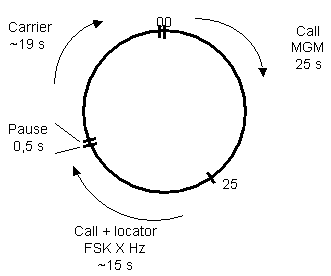
The sequence cycle should not be to long. Today most beacons use a cycle of about 30-40 s depending on the total message. I order to identify it self while providing both MGM, CW and a carrier 60 s sounds like the right choice. In the sequence in fig. 1 the MGM begins at 0 s. The "call + locator" begins at 25 s followed by a 0,5 s pause before the carrier is sent until 59,5 s followed by a 0,5 s pause until 60 s. Using this sequence will fix both existing CW ID and carrier requirements and adding the new MGM for mixed mode purposes.
The frequency shift, if used for the CW ID, is 250 Hz below 1 GHz and 400 Hz above. However, the shift above 1 GHz may be subject to change.
The Next Generation Beacons platform is based upon a VCO-PLL controlled Direct Digital Synthesiser (DDS). It has many advantages when it comes to phase noise performance and frequency agility among others.
Fig. 2. Basic topology.

The problem with the basic topology is when the operating frequency becomes to high. Then the phase noise from the DDS becomes critical. This may be the case if multiplication of the DDS frequency is used. E.g. multiplying a 1 GHz signal 24 times to achieve 24 GHz results in to much phase noise. There are "reverse DDS" methods to deal with this issue but they lack the flexibility of frequency changes. In a reverse DDS microwave beacon the "normal" crystal/OCXO, besides working as oscillator, also clocks the DDS which then is set to generate an output frequency of 10 MHz. This frequency is then compared with the GPS reference and phase compared and the output controls the crystal/OCXO.
An alternative topology is based on a programmable XO/VCXO like the Si570. This solution is cheap and fairly simple to implement. However, due to its phase noise performance and PLL setup time this was ruled out at an early stage.
The Next Generation Beacons project has and have the aim to develop a relevant and open platform that can be used by "any" beacon site and to assist others getting on board the next generation of beacons. The requirements are:
PAs are, as such, not part of the fundamental design but relevant for OZ7IGY to optimise the overall efficiency.
The beacon platform is divided into functional blocks due to the core functionality plus service and maintenance flexibility. In case one DDS boards fails it may be swapped with one from a "less popular" frequency. Therefore the filter and buffer board is not integrated with the DDS board.
Fig.3. Functional block diagram consisting of the GPS frequency and time reference, 1 GHz VCO-PLL and DDS units. The optional distribution boards, service management and PA chain are also shown.
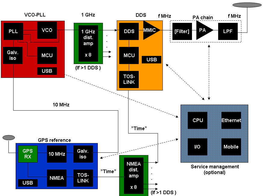
Using the topology in fig. 3. it is be possible to reach 432 MHz directly and also 1,3 GHz by using over-sampling (per Analog Devices application note 939 "Super Nyquist"). This principle is used for OZ7IGY. Above 1,3 GHz it is recommended to either
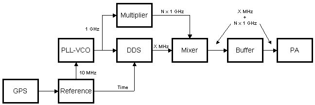
When using a 1 GHz clock and an AD9912 it is fairly easy to reach 2 GHz + 320 MHz (2,3 GHz), 3 GHz + 400 MHz (3,4 GHz), 6 GHz - 240 MHz (5,7 GHz) and 10 GHz + 368 MHz (10 GHz). 24 GHz may be reached by using the same mixing principle and then multiply the signal because 48 MHz is close (24,000 GHz vs 24,048 GHz).
Fig.4. SHF beacon using same functional blocks, multiplication of low noise VCO-PLL (Crystek) and mixing.
Presentation made at the RSGB Convention October 2018
Presentation made at the Friedrichshafen Ham Radio June 2015
Presentation made at the Martlesham Microwave Round Table April 2015
Concept and hardware presentation made during the autumn of 2011
The project team consist of the following members:
| Finn | OZ1AHV | GPS antenna |
| Jørgen | OZ1BNN | Maintenance |
| Brian | OZ1BV | WB6DHW boards and software |
| Poul-Erik | OZ1CKG | PI4 decoding and DDS programming |
| Thomas | OZ2CPU | VCO software |
| Michael | OZ2ELA | All H/W designs and PCBs |
| Bo | OZ2M | Project management, PI4 specification, DDS and PLL programming and web |
| Arne | OZ5GQ | Assembly and measurements |
| Mogens | OZ5LP | Digital H/W and embedded S/W |
| Steen | OZ5N | H/W development |
| Per | OZ8PG | Assembly |
| Henning | OZ9GE | Assembly, DDS tests and measurements |
| Jens Ole | OZ9ZZ | Assembly, DDS tests and tools |
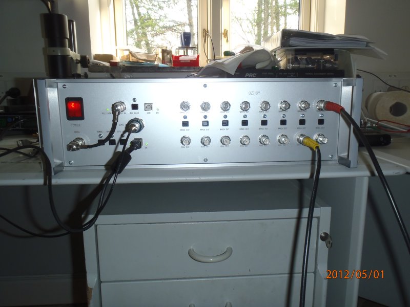
The "reference box" during test. The "reference box" contains the GPS locked 10 MHz and NMEA outputs, 1 GHz VCO-PLL and distribution amplifier boards for 10 MHz, 1 GHz and NMEA signals. Please not that for the Next Generation Beacons platform the 10 MHz board is not needed.
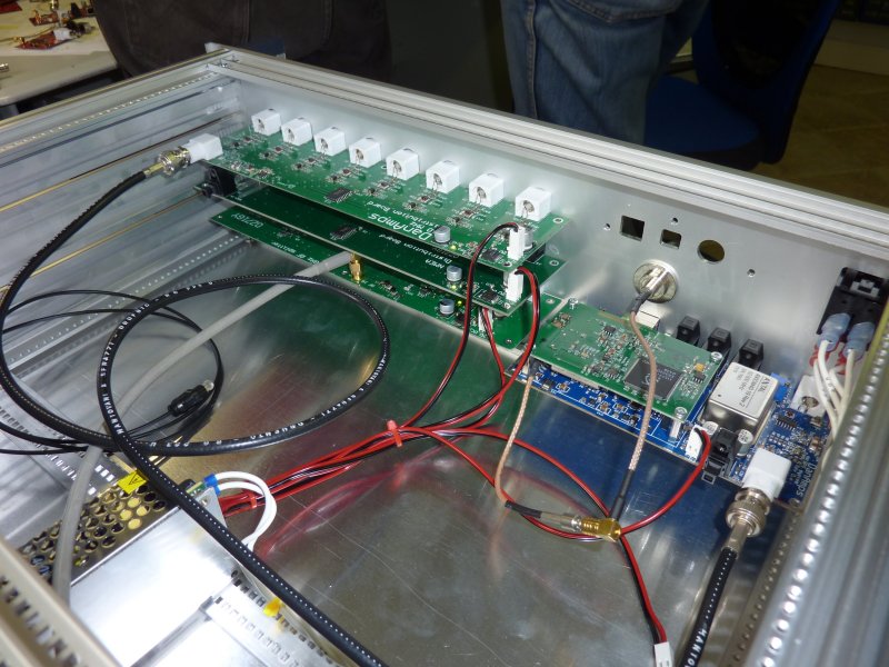
Inside view of the "reference box" before the VCO-PLL is installed. Left stack (bottom to top) is the 1 GHz distribution board, NMEA distribution board and the 10 MHz distribution board. The 10 MHz board is Right side is the GPS 10 MHz reference boards. Please not that for the Next Generation Beacons platform the 10 MHz board is not needed.
Reference box, 50 MHz and 144 MHz beacons during burn-in.
![]()
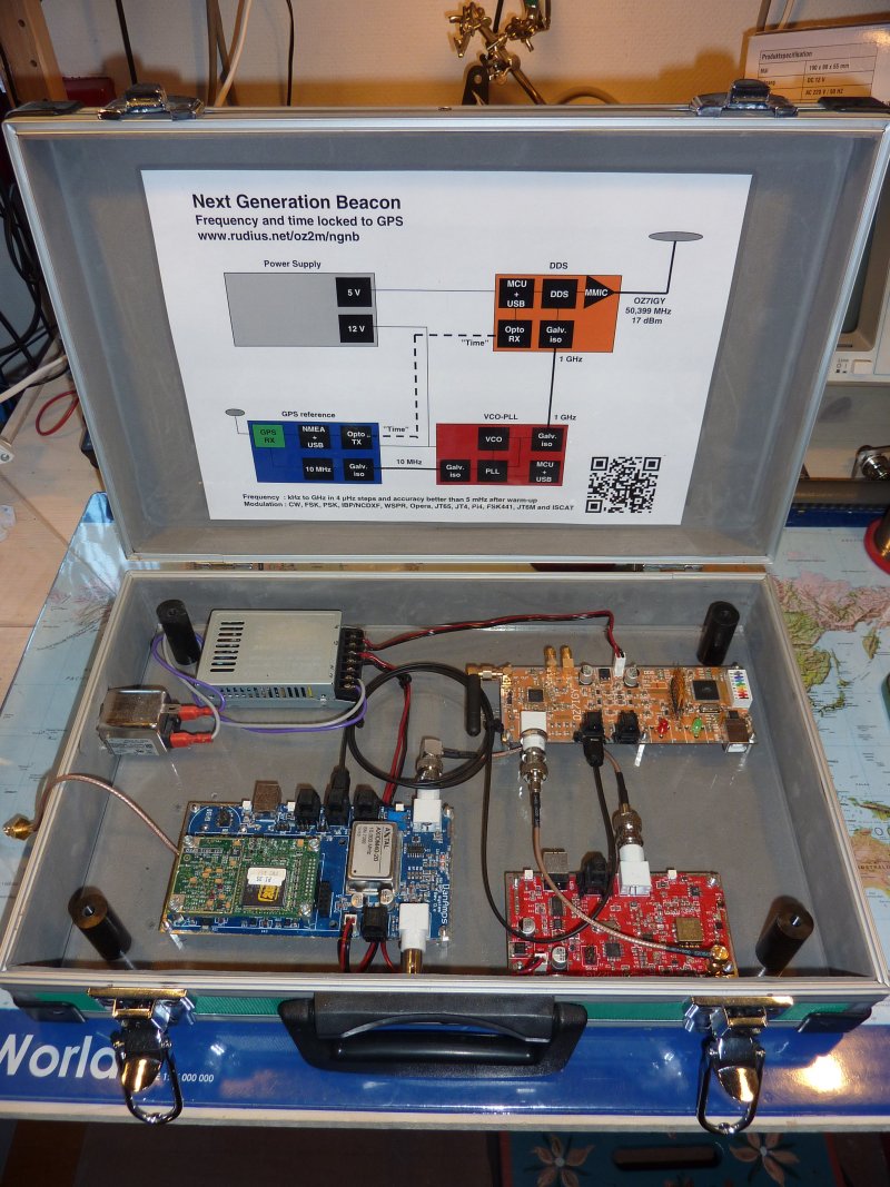
The Next Generation Beacons demo box is a self contained all-in-one beacon fitted into a small suitcase. It includes the GPS 10 MHz oscillator, a 1 GHz VCO and a DDS board all connected to a power supply.
Please contact Bo, OZ2M, at my call sign @ this domain.
Bo, OZ2M, www.rudius.net/oz2m