2018-12-28
| Overview | VCO-PLL | DDS | GPS reference | Distribution amplifiers | Service management | Sequence | PI4 | Software |
The S/W is made with the free Atmel Studio version 7.0.1931.
To use the Next Generation Beacons DDS software you must program the ATmega128A with the Multimode.hex file via the 6 pin ICSP on the DDS unit.
The OZ7IGY Beacon Next Generation Beacons platform implementation Multimode.c/h, management.c/h, common.c/h, morse.c/h, pi4.c/h, jt4.c, jt65.c/h, reedsolomon.c/h, wspr.c/h, opera.c/h, fsk441.c/h, jt6m.c/h, iscat.c/h, jt9_t10.c/h, msk144.c/h, ft8.c/h and qra64.c/h Poul-Erik Hansen, OZ1CKG and Bo Hansen, OZ2M
ISCAT, FSK441, FT8, JT4, JT6M, JT65, JT9, MSK144, QRA64 and WSPR
Implementation by Joseph H. Taylor Jr., K1JT and Steven J. Franke, K9AN (FT8)
PI4
Documentation by Bo Hansen, OZ2M
JT4 and WSPR
Documentation by Andy Talbot, G4JNT
JT65
Visual C++.net by Rick Wakatori, 7L1RLL
Reed-Solomon code by Phil Karn, KA9Q
Opera
Implementation by Jose Alberto Nieto Ros, EA5HVK
Documentation by Guido ten Dolle, PE1NNZ
T10
Documentation by Joseph H. Taylor Jr., K1JT (JT9) and Igor Chernikov, UA3DJY
Multimode is free software: you can redistribute it and/or modify it under the terms of the GNU General Public License as published by the Free Software Foundation, either version 3 of the License, or (at your option) any later version.
Multimode is distributed in the hope that it will be useful, but WITHOUT ANY WARRANTY; without even the implied warranty of MERCHANTABILITY or FITNESS FOR A PARTICULAR PURPOSE. See the GNU General Public License for more details: www.gnu.org/licenses
Here is a quick guide that will get you started. It is assumed you know how to program an Atmel microcontroller in your preferred program and how to use a simple terminal program.
The DDS unit is now setup and will use a 1 minute sequence sending PI4 + CW + carrier at the selected frequency using CW frequency shift keying, receive the GPS NMEA $GPRMC frames at 9600 Baud and 1200 ms between 1 PPS and GPS data string interpreted. If using the exact parameters from the examples above the beacon will send "OZ7IGY" in PI4 and CW at 144,471 MHz and the resulting USB dial, on most radios, will be 144 470 200 for both the MGM, CW and carrier parts.
If you need to fine tune or alter one of the many parameters please see the configuration possibilities in the configuration examples and the EEPROM map section.
Fully embedded symbol encoding of CW, Northern California DX Foundation/International Beacon Project, PI4, Synchronized Beacon Project, JT4, WSPR, JT65, Opera, FSK441, JT6M, ISCAT, JT9, MSK144, FT8, T10 and QRA64 mixed modes of call, square/locator, optional message and power. The submodes can also be set.
The frequency input resolution of the carrier, CW FSK and fundamental MGM-tone is 1 Hz width a maximum resolution of 4 µHz in the DDS. If multiplying the output frequency it is necessary to set a divider ratio and frequency offset in the S/W so the frequency math will be correct. The divider/multiplier can be from 1 to 255 and the frequency offset can be from 0 mHz to 999 mHz.
The maximum calculated frequency deviation from ideal is less than 4 µHz for all modes. The MGM tones can either be relative to a user input frequency or automatically set relative to the CW carrier frequency at a base band frequency of 800 Hz.
The symbol timing is made with a resolution of 125 ns. The maximum deviation from ideal is 51,3 ns or 22,6 PPM (FSK441). The maximum accumulated timing error is 11,1 µs or 48,5 PPM (JT4).
The frequency and time is locked to the Global Positioning System (GPS). The GPS must only output the selected GPS data frame. In case the GPS data frame is missing completely, e.g. due to a broken connection to the DDS unit, the transmission sequence will consist of CW and a fixed length carrier only. The Baud rate setting must match the serial speed of the GPS receiver used. Most GPS receivers output at either 4800 Baud or 9600 Baud. The S/W is designed to use the following data frames with an update rate of 1 second for time synchronization:
Initially no valid GPS signal has been received thus time sensitive transmissions like MGM and frequency multiplexed do not take place. When a valid GPS signal is received time sensitive transmissions are executed. If the GPS signal is invalid, but has previously been valid, the time sensitive transmissions continue until a limit, 1 to 255 sequence cycles, has been reached. If the limit is set to 0 there is no limit and the time sensitive part of the sequence remains to be transmitted. Depending on the quality of the time base in the GPS receiver and the duration of a sequence the limit has to be set accordingly. Some GPS receivers are able to be within one second even if the GPS signal has been lost for one hour.
During the period where the GPS signal is invalid, but has been valid, and the limit has not yet been reached the beacon can do one of two different things:
In GPS receivers there is an inevitable delay between the 1 pulse per second (1 PPS) and the corresponding data frame being received and interpreted at least due to the serial speed. By default this delay is set to 1200 ms and can be set with a resolution of 10 ms and can be from 0 s to 2,55 s.
The signal pause style controls if the beacon transmit CW in on off-keying (OOK or A1A) or frequency shift keying (FSK or F1A). All signal pauses, even non CW, are keyed this way. The CW keying speed can be controlled for each mode. To set the keying speed the duration of a dot must be calculated first.
The CW band ID can be used to identify the beacon and band typically relevant in a beacon cluster where more bands are activated. Users may find it difficult to identify if they copy the beacon on the right band. The CW band ID is a CW character that is transmitted as the last part of the CW message. What character to used is entirely up to the beacon manager.
Most of the MGMs have two messages, 0 and 1. Only the MS modes, i.e. FSK441, ISCAT, JT6M and MSK144 have only one message. Which message to send is controlled by the message number for each MGM. If the message number is set to 2 the beacon alternates between message 0 and message 1.
The messages for each MGM is clear text, e.g. OZ7IGY, and can be set byte for byte or using the relevant MMI commands. The clear text is automatically converted to symbols.
The force MGM message 1 on J12-7 overrides the message selection and always transmit message number 1.
The beacon mode controls the transmitted mode and sequence.
| Beacon mode | Description | Multiplexed | Sequence duration | ||
| Dec | Hex | Time | Freq | ||
| 0 | 0 | Setup mode (default mode) | - | ||
| 1 | 1 | Carrier | 1 s | ||
| 10 | A | CW call and carrier | 30 s | ||
| 11 | B | CW call, locator and carrier | 30 s | ||
| 12 | C | CW call, locator and carrier | 1 min | ||
| 13 | D | CW call, locator, message and carrier | 1 min | ||
| 14 | E | CW call and carrier | 1 min | ||
| 15 | F | CW call, message and carrier | 30 s | ||
| 16 | 10 | CW call, message and carrier | 1 min | ||
| 17 | 11 | CW call, locator and 20 s carrier loop (no GPS needed) | >30 s | ||
| 18 | 12 | CW + four dashes - International Beacon Project | 3 min | ||
| 20 | 14 | PI4, CW call, locator and carrier | 1 min | ||
| 21 | 15 | PI4, CW call, locator and carrier - Syncronized Beacon Project (SBP) over five time intervals. The SBP frequencies are not subject to the frequency offsets and divider ratios used in frequency calculations. PI4 message 1 is used on the SBP frequency | X | 1 min/5 min | |
| 22 | 16 | PI4, CW call, locator and carrier - Syncronized Beacon Project (SBP) and normal frequency over five time intervals and two frequencies sets. The frequencies are not subject to the frequency offsets and divider ratios used in frequency calculations. PI4 message 0 is used on the normal frequency and PI4 message 1 is used on the SBP frequency | X | X | 1 min/5 min |
| 30 | 1E | JT4, CW call and locator | 1 min | ||
| 31 | 1F | JT4 even minute CW call and locator and carrier odd minute | 2 min | ||
| 32 | 20 | JT4, CW call and locator and carrier even minute start xx:00, CW call and locator and carrier odd minute 01:30 | 2 min | ||
| 40 | 28 | WSPR, CW call | 2 min | ||
| 41 | 29 | WSPR - time multiplexed over eight intervals (fixed frequency) | X | 2 min to 16 min | |
| 42 | 2A | WSPR - time and frequency multiplexed over 15 intervals. The frequencies are not subject to the frequency offsets and divider ratios used in frequency calculations | X | X | 2 min to 30 min |
| 50 | 32 | JT65 and carrier | 1 min | ||
| 51 | 33 | JT65 even minute CW call and locator and carrier odd minute | 2 min | ||
| 52 | 34 | JT65x2, CW call, locator and carrier | 1 min | ||
| 53 | 35 | JT65, CW call and locator | 1 min | ||
| 54 | 36 | JT65, CW call and locator and carrier even minute start xx:01, CW call and locator and carrier odd minute 01:30 | 2 min | ||
| 60 | 3C | Opera, CW call and locator | Varies | ||
| 70 | 46 | FSK441 30 s, CW call, locator and carrier | 1 min | ||
| 80 | 50 | JT6M 30 s, CW call, locator and carrier | 1 min | ||
| 90 | 5A | ISCAT 30 s, CW call, locator and carrier | 1 min | ||
| 100 | 64 | JT9, CW call, locator and carrier | Varies | ||
| 101 | 65 | JT9 even minute CW call and locator and carrier odd minute | Varies | ||
| 110 | 6E | MSK144, CW call, locator and carrier | 1 min | ||
| 120 | 78 | FT8, CW call, locator and carrier | 1 min | ||
| 130 | 82 | T10, CW call, locator and carrier | 1 min/2 min | ||
| 131 | 83 | T10 even minute CW call and locator and carrier odd minute | 2 min | ||
| 140 | 8C | QRA64, CW call and locator | 1 min | ||
| 141 | 8D | QRA64 even minute CW call and locator and carrier odd minute | 2 min | ||
| 142 | 8E | QRA64, CW call and locator and carrier even minute start xx:01, CW call and locator and carrier odd minute 01:30 | 2 min | ||
A test carrier can also be set, turned on and off.
If a different sequence is wanted it is easy to copy one of the existing ones and modify it to the specific purpose.
For QRA64 the symbols have to be entered instead of the messages. Use QRA64Code.exe by Joe, K1JT to generate the symbols then use BeaconManager, 1.2.0 or later, to load them.
The power level. Currently only used in the WSPR protocol and must end with a 0, 3 or 7, e.g. 30 dBm, 43 dBm.
It is possible to set most of the default parameters in one go by evoking the wr defaults MMI command. This saves time and minimizes setup errors.
On the auxiliary control connector, J12, next to the MCU the below signals are available for external control and display.
| J12-pin | Port F-pin | Functionality | Direction | Active |
| 1 | 0 | Power level bit 0, e.g. 0#: IBP 100 W, 01: IBP 10 W, 10: IBP 1 W and 11: IBP 100 mW | Output | High |
| 3 | 1 | Power level bit 1, e.g. #0: IBP 100 W, 01: IBP 10 W, 10: IBP 1 W and 11: IBP 100 mW | Output | High |
| 5 | 2 | "Kill switch". Stops the transmission sequence after completing current sequence and waits for release. Kill switch idle mode controls if it is active high (connect pull-down resistor) or low (internally pulled up) | Input | High/Low |
| 7 | 3 | Force MGM message 1 when starting the sequence, e.g. for service message (internally pulled-up) | Input | Low |
| 9 | 4 | GPS valid. Checked during carrier/idle period only. Connect to green LED via 390 Ω | Output | High |
| 11 | 5 | TX "modulation". During the MGM part it flashes at half symbol rate. Flashes in sync with CW and on when carrier. Connect to red LED via 390 Ω | Output | High |
| 13 | 6 | PA on signal. Can be used to control if the PA should be switched off during idle periods e.g. in time multiplexed modes like IBP, SBP and WSPR intervals and hopping | Output | Low |
| 15 | 7 | On-off keying. Can be used to key external amplifier stage for improved on-off keying isolation and key click | Output | Low |
All the even pin numbers on J12 are connected to ground.
The upper four bits are used in frequency multiplexed beacon modes.
| SW1-pin | Port F-pin | Functionality | Direction | Active |
| 1 | 0 | Override bit 0 | Input (internally pulled-up) | High |
| 2 | 1 | Override bit 1 | Input (internally pulled-up) | High |
| 3 | 2 | Override bit 2 | Input (internally pulled-up) | High |
| 4 | 3 | Override bit 3 | Input (internally pulled-up) | High |
| 5 | 4 | Frequency index bit 0 | Output | High |
| 6 | 5 | Frequency index bit 1 | Output | High |
| 7 | 6 | Frequency index bit 2 | Output | High |
| 8 | 7 | Frequency index bit 3 | Output | High |
In beacon mode 0x16/22 (SBP and normal time and frequency multiplexing) the normal frequency is identified as 1 and the SBP is identified as 2.
In beacon mode 0x2A/42 (WSPR frequency multiplexing) the higher four bits identifies the transmission index ranging from 1 to 15 and if the time fails the bits are all zero (0000). The DIP switch is a manual override of the automatic selection of transmission index. When all are set to zero (0000) the beacon is in automatic mode transmission index mode.
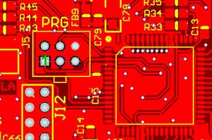
Programming the ATmega128A takes place via the 6 pin ICSP connector just next to the MCU. Pin 1 is the pin closest to the center of the DDS PCB.
Use a 6 pin Atmel ICSP compatible programmer, e.g. the original Atmel AVRISP mkII or one of the many cheaper clones available, e.g. USBasp and eXtreme Burner.
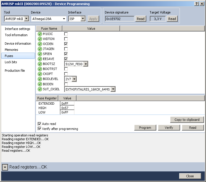
Program the ATmega128A fuses as show below. This operation only has to be performed the first time you program the specific ATmega128A.
| Fuse | Next Generation Beacons |
| M103C | [ ] |
| WDTON | [ ] |
| OCDEN | [X] |
| JTAGEN | [ ] |
| SPIEN | [X] |
| EESAVE | [X] |
| BOOTSZ | 512W_FE00 |
| BOOTRST | [ ] |
| CKOPT | [ ] |
| BODLEVEL | 2V7 |
| BODEN | [ ] |
| SUT_CKSEL | EXTHIFXTALRES_16KCK_64MSEXTENDED |
| EXTENDED | 0xFF (valid) |
| HIGH | 0x57 (valid) |
| LOW | 0xFF (valid) |
Example of fuses programming using Atmel Studio (Menu | Tools | Device Programming | Fuses).
Program the Multimode.hex file into the flash memory using your preferred programming software. Below is an example of .hex file programming using Atmel Studio (Menu | Tools | Device Programming | Memories). Please note that if the ATmega128A has been used for another program than Multimode it is recommended to perform a complete Device | Erase Chip before programming the Multimode software and configuring it.
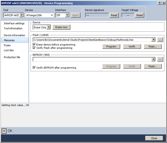
In case you mess up the settings really bad you may choose to program the Multimode_Rescue_EEPROM.hex file to the EEPROM. It will bring back the settings to default, call sign to OZ7IGY, locator to JO55WM and set the frequency to 50,399 MHz. You may also simply use the Device | Erase Chip feature and start from scratch.
The man machine interface is BeaconManager or a simple terminal program, e.g. Termite (Windows) or CuteCom (Linux), connected to the USB port at 9600 Baud 8N1. Transmitted text must only have <LF> appended. If you experience problems with connecting to the DDS unit it is most likely related to the FTDI FT232R drivers. If so please consult the FTDI Installation Guides.
Using BeaconManager.
![]()
Using Termite.
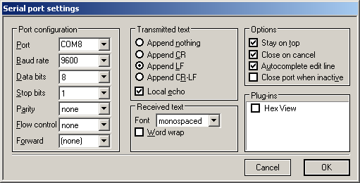
The DDS unit identifies itself with the DDS> prompt. All input to the DDS unit must be in lower case. All output from the DDS is in upper case except variable names. All addresses (0 to FFF) and byte values (0 to FF) are in hex. Hex values must not have the 0x-prefix. All frequency inputs are in Hz.
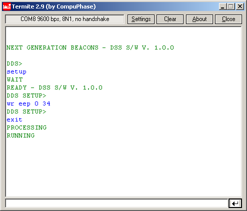
Each parameter byte can be found in the DDS unit EEPROM map. Each EEPROM byte can be read or written byte by byte or a number of commands can be evoked. E.g. to change the beacon mode write
wr eep 0 BEACONMODE
where BEACONMODE is the relevant hex byte from the beacon mode table, and press enter.
To omit e.g. a locator from a CW message set the first byte of the locator in the EEPROM to 0.
| Command | Description |
| rd eep ADDRESS [COUNT] | Read the EEPROM value at ADDRESS and with an optional COUNT parameter if wanting to read more than one byte, e.g. rd eep 2e. Max COUNT is 16 |
| rd eep *16 | Read the EEPROM values, at all addresses, and print 16 bytes per line |
| rd act | Read the active beacon mode variables. Some
lines are only printed if applicable for the relevant beacon mode.ACTIVE PARAMETERS ================= hex/dec BeaconMode : 14 / 20 The beacon mode is PI4 (20-29) SignalPauseStyle: 01 / 1 The signal pause style is frequency shift keying (1), OOK (0) SetupCarrier : 01 / 1 The setup carrier mode: 0: disabled, 1: Enabled at CW/carrier frequency KillSwitchIdle : 01 / 1 The kill switch idle mode: 0: idle is low, 1: idle is high FREQFrequency : 50471000 The CW carrier frequency in Hz (decimal) FSKFrequency : 50470750 The CW FSK frequency IF used in Hz (decimal) MGMFrequency : 0 The lowest MGM frequency in Hz, if 0 then auto frequency relative to FREQFrequency (decimal) FreqDivider : 01 / 1 The frequency divider for all internally calculated MGM frequencies CW/FSK/MGMoffset: 0/0/0 The carrier, FSK and MGM frequency offsets in mHz for all multiplied/divided frequencies GPSBaud : 33 / 51 The GPS data Baud rate MCU value GPS1PPSNMEA : 78 / 120 The 1 PPS to GPS data string delay in 10 ms resolution, thus 120 x 10 = 1200 ms GPSSignalLoss : 00 / 0 The GPS signal lost or invalid value, 0: Do nothing, 1: Carrier GPSStatusLimit : 1E / 30 The number of sequence cycles before doing something about it, 0: Disabled GPSDataFormat : 00 / 0 The GPS data string format, 0: NMEA $GPRMC, 1: NMEA $GPGGA, 2: Motorola @@Ea GPSEcho : 00 / 0 The GPS echo parameter, 0: Disabled, 1: Enabled CWDotDuration : 64 / 100 The CW dot duration in ms CWCall : OZ7IGY The CW call sign CWLocator : JO55WM The CW locator CWMsg : The optional CW message CWBandID : The CW BandID PowerLevel : 2B / 43 The power level SBPFrequency : 50007000 The SBP frequency in Hz (decimal) IntervalMask : 01 / 1 The transmission interval mask. Binary 00000001 where intervals are numbered 76543210 SBPCall : OZ7IGY/S The SBP CW call sign HOPPING DATA ------------ Intervals : 0F / 15 The number of intervals in the time and frequency multiplexed sequence 00: 1 137500 A transmission that is included in the sequence 01: 1 475700 02: 1 1838100 03: 0 3594100 A transmission that is skipped yet time slot is still in the sequence 04: 1 5288700 05: 1 7040100 06: 0 10140200 07: 0 14097100 08: 1 18106100 09: 1 21096100 10: 1 24926100 11: 1 28126100 12: 1 50390000 13: 1 43239000 14: 1 29639000 Super Nyquist mode 296 MHz is also imaged on 1296 MHz DDS cur. (hex) : 7F / 127 The DDS DAC current (the heights eight bits of the total ten bits) MGMSubMode (hex): 28 / 40 The MGM submode MGMMsgNo : 00 / 0 The MGM message number MGMMsg0 : OZ7IGY The first MGM message FT83BitsMsg0 : 00 / 0 The first FT8 three bits (FT8 only) MGMMsg1 : OZ7IGY/S The second MGM message FT83BitsMsg1 : 00 / 0 The second FT8 three bits (FT8 only)The lines below are only printed if the Multimode S/W is recompiled with the #define RdActFull enabled in the common.h file. They are typically only useful during S/W development and testing. MGMSymbols : 146 The number of symbols MGMMsgRepeats : 1 The number of times the message is repeated per cycle SYMBOLS ------- 000: 02 02 The values for symbol 0 for message 0 and 1 001: 02 02 ... 144: 03 01 145: 03 03 The values for symbol N for message 0 and 1 MIN: 00 00 The lowest symbol values for message 0 and 1 MAX: 03 03 The highest symbol values for message 0 and 1 FTW CARRIERS (HEX) ------------------ 00: 0C E6 F0 F1 6F 44 The FTW for symbol value 0 01: 0C E6 F4 E0 11 4D 02: 0C E6 F8 CE B3 57 03: 0C E6 FC BD 55 60 The FTW for the highest symbol value number 65: 00 00 00 00 00 00 The FTW for the off carrier (always 0) 66: 0C E6 EE B7 02 61 The FTW for the FSK carrier 67: 0C E6 F2 E8 C0 49 The FTW for the CW carrier 68: 00 00 00 00 00 00 The FTW for the test carrier The Frequency Tuning Word (FTW) can be converted into a frequency by using the following formula:
|
| Command | Description |
| wr eep ADDRESS VALUE | Write a byte VALUE to the EEPROM at ADDRESS both address and value are in hex without leading 0x, e.g. wr eep 0 1e |
| wr call CALLSIGN | Write the CALLSIGN to the EEPROM, max length is 15 characters, e.g. wr call oz7igy |
| wr loc LOCATOR | Write the LOCATOR to the EEPROM, max length is six characters, e.g. wr loc jo55wm |
| wr msg MESSAGE | Write the MESSAGE optional message to the EEPROM, max length is six characters, e.g. wr msg aur |
| wr bandid CHARACTER | Write the CHARACTER bandID to the EEPROM, max length one character, e.g. wr bandid a |
| wr freq FREQUENCY | Write the carrier FREQUENCY in Hz to EEPROM, min is 0 Hz and max is 433 MHz, e.g. wr freq 144471000 (base 10) |
| wr fsk FREQUENCY | Write the CW FSK FREQUENCY in Hz to EEPROM, min is 0 Hz and max is 433 MHz, e.g. wr fsk 144470750 (base 10) |
| wr hop INDEX MODE FREQUENCY | Write the MODE, 0: skip, 1: transmit, and FREQUENCY in Hz for WSPR frequency hopping INDEX (base 10) |
| wr mgm FREQUENCY | Write the lowest MGM carrier FREQUENCY in Hz to EEPROM, min is 0 for auto MGM frequency relative to the CW/carrier frequency, otherwise 1 Hz and max is 433 MHz e.g. wr mgm 144471000 (base 10) |
| wr multi DIVIDER CAROFFSET FSKOFFSET MGMOFFSET | Write the DIVIDER, CAROFFSET, FSKOFFSET and
MGMOFFSET in mHz to EEPROM, divider
min is 1 and max is 255 and offsets are 0 mHz to 999 mHz e.g. wr multi 32
500 700 0 The MGMOFFSET is not used in case of automatic calculation of the MGM frequencies relative to the carrier frequency, i.e. when the MGM frequency is 0 (base 10) |
| wr fsk441 msg 0 MESSAGE | Write the FSK441 MESSAGE 0 to EEPROM. Max eight characters and replace space " " with an underscore "_", e.g. wr fsk msg 0 oz7igy |
| wr ft8 msg # MESSAGE | Write the FT8 MESSAGE 0 or 1 to EEPROM. Max 13 characters and replace space " " with an underscore "_", e.g. wr ft8 msg 0 oz7igy_jo55wm. The three additional bits have to be set using the wr eep ADDRESS VALUE command |
| wr iscat msg 0 MESSAGE | Write the ISCAT MESSAGE 0 to EEPROM. Max eight characters and replace space " " with an underscore "_", e.g. wr iscat msg 0 oz7igy |
| wr jt4 msg # MESSAGE | Write the JT4 MESSAGE 0 or 1 to EEPROM. Max 13 characters and replace space " " with an underscore "_", e.g. wr jt4 msg 0 oz7igy_jo55wm |
| wr jt6m msg 0 MESSAGE | Write the JT6M MESSAGE 0 to EEPROM. Max eight characters and replace space " " with an underscore "_", e.g. wr jt6m msg 0 oz7igy |
| wr jt65 msg # MESSAGE | Write the JT65 MESSAGE 0 or 1 to EEPROM. Max 13 characters and replace space " " with an underscore "_", e.g. wr jt65 msg 0 oz7igy_jo55wm |
| wr jt9 msg # MESSAGE | Write the JT9 MESSAGE 0 or 1 to EEPROM. Max 13 characters and replace space " " with an underscore "_", e.g. wr jt9 msg 0 oz7igy_jo55wm |
| wr msk144 msg 0 MESSAGE | Write the MSK144 MESSAGE 0 to EEPROM. Max eight characters and replace space " " with an underscore "_", e.g. wr msk144 msg 0 oz7igy |
| wr opera msg # MESSAGE | Write the Opera MESSAGE 0 or 1 to EEPROM. Max six characters and replace space " " with an underscore "_", e.g. wr opera msg 0 oz7igy |
| wr pi4 msg # MESSAGE | Write the PI4 MESSAGE 0 or 1 to EEPROM. Max eight characters and replace space " " with an underscore "_", e.g. wr pi4 msg 0 oz7igy |
| wr t10 msg # MESSAGE | Write the T10 MESSAGE 0 or 1 to EEPROM. Max 13 characters and replace space " " with an underscore "_", e.g. wr t10 msg 0 oz7igy_jo55wm |
| wr wspr msg # MESSAGE | Write the WSPR MESSAGE 0 or 1 to EEPROM. Max six characters and replace space " " with an underscore "_", e.g. wr wspr msg 0 oz7igy |
| wr defaults | Write the following default parameters to the EEPROM in one
go:
|
| Command | Description |
| setup | To enter setup mode |
| exit | To leave setup mode |
| carr freq FREQUENCY | Send a carrier at FREQUENCY, e.g. carr freq 50399000 will send a carrier at 50,399 MHz. Alternatively the FREQUENCY is a FTW carrier number, i.e. 0 to the maximum FTW number and from 65 to 68 |
| carr on | Turns the test carrier on |
| carr off | Turns the test carrier off |
| Response | Description |
| DDS> | The DDS prompt |
| DDS SETUP> | The DDS setup prompt |
| INVALID DATA | The call sign, locator or message command is invalid |
| INVALID FREQUENCY | The frequency command is invalid |
| INVALID MGM DATA | The MGM data command is invalid |
| NEXT GENERATION BEACONS - DSS S/W V. #.#.# | MCU power up welcome message |
| OK | Command accepted |
| PROCESSING | Processing changes performed during setup. Happens after an "exit" command if any changes were made |
| READY - DDS S/W V. #.#.# | In setup mode now and the S/W version number |
| RUNNING | Response when the S/W is back in a normal transmission cycle |
| UNKNOWN COMMAND | The MMI command could not be identified |
| WAIT | Setup mode is called but waiting for transmission cycle to complete |
When the GPS echo is enabled, typically for troubleshooting the GPS, all received GPS data is echoed one-to-one on the USB port, e.g. the $GPRMC frame. Furthermore, are the control variables also printed on the USB port just before the carrier begins, for sequences that include a carrier, or just before the transmission cycle begins for sequences without carrier.
| Control variable | Description |
| Status | The GPS status
|
| Limit | The non valid GPS limit value (static) |
| Count | The number of sequence cycles that a valid time sync has failed and/or GPS signal is invalid. Max value is 255 |
| Result | The minute value from the GPS data, 0-59. If Result is -1 then time is deemed as unreliable |
The GPS echo is enabled by evoking the wr eep 23 1 command and disabled by the wr eep 23 0 command. Please note that enabling the GPS echo delays the beacon time stamp with about 50 ms.
In the below examples the beacon call sign is OZ7IGY and the locator is JO55WM.
The enter the setup mode write setup at the DDS> prompt. To exit the setup mode write exit at the DDS SETUP> prompt.
All commands are followed by pressing the enter key. The sequence of commands executed in the setup mode is not important.
To view the changes write rd act at the DDS SETUP> prompt.
In this example the sequence is PI4 + CW + carrier at 144,471 MHz.
The change beacon mode from PI4 + CW + carrier to e.g. JT65 + CW + carrier + CW + carrier only the following commands are different:
In this example the sequence is PI4 + CW + carrier at 10368,930 MHz and the DDS is followed by a x 32 multiplier chain, i.e. the DDS carrier frequency is 324,0290625 MHz.
In this example the sequence is PI4 + CW + carrier at 1296,930 MHz using the Super Nyquist second image.
In the Synchronized Beacon Project the beacon only transmit in one of the five one minute long time slots. Which frequency and time slot to use should be obtained from the SBP Network Coordinator.
In this example the SBP time slot is 2, i.e. transmitting in the minutes beginning with 2, 7, 12, 17 ..., and the frequency is 50,007 MHz.
In the Synchronized Beacon Project the beacon only transmit in one of the five one minute long time slots. Which frequency and time slot to use should be obtained from the SBP Network Coordinator. In the remainder of the time slots the beacon transmits on its normal allocated frequency.
In this example the SBP time slot is 3, i.e. transmitting in the minutes beginning with 3, 8, 13, 18 ..., and the SBP frequency is 50,005 MHz. The normal frequency for the beacon is 50,471 MHz.
Normal part
SBP part
In this example the DDS unit is used as a WSPR hopping transmitter on five different frequencies of which one is suspended.
In this example the GPS serial speed is 9600 Baud, the NMEA frame is $GPRMC and the 1 PPS to real time delay is 1300 ms.
Via the EEPROM map you can get access to the individual bytes used for configuring the DDS unit. You can use this to fine tune the various parameters.
| EEPROM address | Type | Description | MMI command | |
| Dec | Hex | |||
| 0000 | 0000 | Value | Beacon mode. See beacon mode table | |
| 0001 | 0001 | Value | Signal pause style on-off keying or FSK. 0: OOK, 1: FSK. Default is 1 = FSK | |
| 0002 | 0002 | Value | Frequency for DDS clock byte 0 (variable not implemented) | |
| 0003 | 0003 | Value | Frequency for DDS clock byte 1 | |
| 0004 | 0004 | Value | Frequency for DDS clock byte 2 | |
| 0005 | 0005 | Value | Frequency for DDS clock byte 3 | |
| 0006 | 0006 | Value | Frequency for CW FSK byte 0 | wr fsk FREQUENCY |
| 0007 | 0007 | Value | Frequency for CW FSK byte 1 | |
| 0008 | 0008 | Value | Frequency for CW FSK byte 2 | |
| 0009 | 0009 | Value | Frequency for CW FSK byte 3 | |
| 0010 | 000A | Value | Frequency for CW carrier byte 0 | wr freq FREQUENCY |
| 0011 | 000B | Value | Frequency for CW carrier byte 1 | |
| 0012 | 000C | Value | Frequency for CW carrier byte 2 | |
| 0013 | 000D | Value | Frequency for CW carrier byte 3 | |
| 0014 | 000E | Value | Frequency for MGM carrier 0 byte 0 | wr mgm FREQUENCY |
| 0015 | 000F | Value | Frequency for MGM carrier 0 byte 1 | |
| 0016 | 0010 | Value | Frequency for MGM carrier 0 byte 2 | |
| 0017 | 0011 | Value | Frequency for MGM carrier 0 byte 3 | |
| 0018 | 0012 | Value | Frequency divider used if output it multiplied externally. Default is 1, i.e. no dividing | wr multi DIVIDER CWOFFSET FSKOFFSET MGMOFFSET |
| 0019 | 0013 | Value | CW/carrier frequency offset in mHz, if output it multiplied externally, byte 0. Default is 0, i.e. no offset | |
| 0020 | 0014 | Value | CW/carrier frequency offset in mHz, if output it multiplied externally, byte 1. Default is 0, i.e. no offset | |
| 0021 | 0015 | Value | FSK frequency offset in mHz, if output it multiplied externally, byte 0. Default is 0, i.e. no offset | |
| 0022 | 0016 | Value | FSK frequency offset in mHz, if output it multiplied externally, byte 1. Default is 0, i.e. no offset | |
| 0023 | 0017 | Value | MGM frequency offset in mHz, if output it multiplied externally, byte 0. Default is 0, i.e. no offset | |
| 0024 | 0018 | Value | MGM frequency offset in mHz, if output it multiplied externally, byte 1. Default is 0, i.e. no offset | |
| 0025 | 0019 | Value | Transmit a carrier when entering the setup mode. Default is 1, i.e. transmit carrier | |
| 0026 | 001A | Value | Kill switch idle mode. Default is 1, i.e. idle is high | |
| 0027 | 001B | Value | Number of intermediate frequency steps used when changing frequency. Default is 0, i.e. no intermediate steps | |
| EEPROM address | Type | Description | |
| Dec | Hex | ||
| 0030 | 001E | Value | GPS serial speed (See ATmega128A datasheet table 20-11, 9600 Baud at 8 MHz clock, UX2=0). Default is 51/0x33 for 9600 Baud. 103/0x67 for 4800 Baud |
| 0031 | 001F | Value | 1 PPS to corresponding data frame interpreted delay. The delay can be from 0 s to 2,55 s with a resolution of 10 ms. Default is 120/0x78 equal to 1200 ms |
| 0032 | 0020 | Value | GPS is present and invalid but has previously been present and valid:
Used in combination with the sequence cycles limit at address 33/0x21. |
| 0033 | 0021 | Value | Number, 1 to 255, of sequence cycles before omitting the MGM part of the sequence. If set to 0 then the MGM is always sent, if applicable, even if the GPS signal is lost or invalid. Default is 30 |
| 0034 | 0022 | Value | The GPS time data frame used:
|
| 0035 | 0023 | Value | Controls if the GPS data received is echoed to the
management port but only when the DDS unit searches for the time. Also
prints out the value of the GPSStatus, GPSStatusLimit, GPSStatusCount and Result
variables.
This parameter can be used for GPS debugging but delays the sequence by about 50 ms. |
| EEPROM address | Type | Description | |
| Dec | Hex | ||
| 0040 | 0028 | Value | Power level EIRP in dBm. Currently only used in WSPR. Therefore the dBm value must end with either 0, 3 or 7. Otherwise decoding in WSPR will be wrong |
| EEPROM address | Type | Description | |
| Dec | Hex | ||
| 0060 | 003C | Value | The DDS DAC current level. Sets the output power and affects the harmonics and spurious levels. Default is 0x7F similar to the value in the AD9912 datasheet. Sets the heighest eight bits of the total ten bits. The lowest two bits are always set to 11 |
| EEPROM address | Type | Description | MMI command | |
| Dec | Hex | |||
| 0100 | 0064 | Value | CW dot duration in ms. Default is 100/0x64 | |
| 0101 | 0065 | ASCII value | CW call sign byte 0 | wr call CALLSIGN |
| 0102 | 0066 | ASCII value | CW call sign byte 1 | |
| 0103 | 0067 | ASCII value | CW call sign byte 2 | |
| 0104 | 0068 | ASCII value | CW call sign byte 3 | |
| 0105 | 0069 | ASCII value | CW call sign byte 4 | |
| 0106 | 006A | ASCII value | CW call sign byte 5 | |
| 0107 | 006B | ASCII value | CW call sign byte 6 | |
| 0108 | 006C | ASCII value | CW call sign byte 7 | |
| 0109 | 006D | ASCII value | CW call sign byte 8 | |
| 0110 | 006E | ASCII value | CW call sign byte 9 | |
| 0111 | 006F | ASCII value | CW call sign byte 10 | |
| 0112 | 0070 | ASCII value | CW call sign byte 11 | |
| 0113 | 0071 | ASCII value | CW call sign byte 12 | |
| 0114 | 0072 | ASCII value | CW call sign byte 13 | |
| 0115 | 0073 | ASCII value | CW call sign byte 14 | |
| 0116 | 0074 | Value | CW call sign byte 15. Always 0 | |
| 0117 | 0075 | ASCII value | CW locator byte 0 | wr loc LOCATOR |
| 0118 | 0076 | ASCII value | CW locator byte 1 | |
| 0119 | 0077 | ASCII value | CW locator byte 2 | |
| 0120 | 0078 | ASCII value | CW locator byte 3 | |
| 0121 | 0079 | ASCII value | CW locator byte 4 | |
| 0122 | 007A | ASCII value | CW locator byte 5 | |
| 0123 | 007B | ASCII value | CW locator byte 6. Always 0 | |
| 0124 | 007C | ASCII value | CW message byte 0 | wr msg MESSAGE |
| 0125 | 007D | ASCII value | CW message byte 1 | |
| 0126 | 007E | ASCII value | CW message byte 2 | |
| 0127 | 007F | ASCII value | CW message byte 3 | |
| 0128 | 0080 | ASCII value | CW message byte 4 | |
| 0129 | 0081 | ASCII value | CW message byte 5 | |
| 0130 | 0082 | Value | CW message byte 6. Always 0 | |
| 0131 | 0083 | ASCII value | CW BandID byte 0 | wr bandid CHARACTER |
| 0132 | 0084 | Value | CW BandID byte 1. Always 0 | |
The CW keying style is managed in the signal pause style parameter found at address 1/0x01. For more details see the General section.
To calculate the CW dot durations use one of the following formulas:
CW speed in words per minute
Dot duration = 1200/speed
e.g. for 12 WPM: Dot duration = 1200/12 = 100 ms
Speed = 1200/dot duration
e.g. for 100 ms: Speed = 1200/100 = 12 WPM
CW speed in letters per minute
Dot duration = 6000/speed
e.g. for 60 LPM: Dot duration = 6000/60 = 100 ms
Speed = 6000/dot duration
e.g. for 100 ms: Speed = 6000/100 = 60 LPM
| EEPROM address | Type | Description | MMI command | |
| Dec | Hex | |||
| 0400 | 0190 | Value | FSK441 mixed mode CW dot duration in ms. Default is 100/0x64 | |
| 0401 | 0191 | Value | FSK441 submode (reserved) | |
| 0402 | 0192 | Value | FSK441 message number (reserved) | |
| 0403 | 0193 | ASCII value | FSK441 message 0 byte 0 | wr fsk441 msg 0 MESSAGE |
| 0404 | 0194 | ASCII value | FSK441 message 0 byte 1 | |
| 0405 | 0195 | ASCII value | FSK441 message 0 byte 2 | |
| 0406 | 0196 | ASCII value | FSK441 message 0 byte 3 | |
| 0407 | 0197 | ASCII value | FSK441 message 0 byte 4 | |
| 0408 | 0198 | ASCII value | FSK441 message 0 byte 5 | |
| 0409 | 0199 | ASCII value | FSK441 message 0 byte 6 | |
| 0410 | 019A | ASCII value | FSK441 message 0 byte 7 | |
| 0411 | 019B | Value | FSK441 message 0 byte 8. Always 0 | |
| EEPROM address | Type | Description | MMI command | |
| Dec | Hex | |||
| 0650 | 028A | Value | FT8 mixed mode CW dot duration in ms. Default is 100/0x64 | |
| 0651 | 028B | Value | FT8 sub mode (reserved) | |
| 0652 | 028C | Value | FT8 message number. Message selector 0, 1 or 2 = alternating. Default is 0 | |
| 0653 | 028D | ASCII/hex value | FT8 message 0 byte 0/digit 0 and 1 | wr ft8 msg 0 MESSAGE |
| 0654 | 028E | ASCII/hex value | FT8 message 0 byte 1/digit 2 and 3 | |
| 0655 | 028F | ASCII/hex value | FT8 message 0 byte 2/digit 4 and 5 | |
| 0656 | 0290 | ASCII/hex value | FT8 message 0 byte 3/digit 6 and 7 | |
| 0657 | 0291 | ASCII/hex value | FT8 message 0 byte 4/digit 8 and 9 | |
| 0658 | 0292 | ASCII/hex value | FT8 message 0 byte 5/digit 10 and 11 | |
| 0659 | 0293 | ASCII/hex value | FT8 message 0 byte 6/digit 12 and 13 | |
| 0660 | 0294 | ASCII/hex value | FT8 message 0 byte 7/digit 14 and 15 | |
| 0661 | 0295 | ASCII/hex value | FT8 message 0 byte 8/digit 16 and 17 | |
| 0662 | 0296 | ASCII | FT8 message 0 byte 9 | |
| 0663 | 0297 | ASCII | FT8 message 0 byte 10 | |
| 0664 | 0298 | ASCII | FT8 message 0 byte 11 | |
| 0665 | 0299 | ASCII | FT8 message 0 byte 12 | |
| 0666 | 029A | ASCII | FT8 message 0 byte 13. Always 0 | |
| 0667 | 029B | Value | FT8 message 0 three bits, ØØØØØxxx | |
| 0668 | 029C | Value | FT8 message 0 message type. 0 = free text, 1 = telemetry. Default is 0 | |
| 0669 | 029D | ASCII/hex value | FT8 message 1 byte 0/digit 0 and 1 | wr ft8 msg 1 MESSAGE |
| 0670 | 029E | ASCII/hex value | FT8 message 1 byte 1/digit 2 and 3 | |
| 0671 | 029F | ASCII/hex value | FT8 message 1 byte 2/digit 4 and 5 | |
| 0672 | 02A0 | ASCII/hex value | FT8 message 1 byte 3/digit 6 and 7 | |
| 0673 | 02A1 | ASCII/hex value | FT8 message 1 byte 4/digit 8 and 9 | |
| 0674 | 02A2 | ASCII/hex value | FT8 message 1 byte 5/digit 10 and 11 | |
| 0675 | 02A3 | ASCII/hex value | FT8 message 1 byte 6/digit 12 and 13 | |
| 0676 | 02A4 | ASCII/hex value | FT8 message 1 byte 7/digit 14 and 15 | |
| 0677 | 02A5 | ASCII/hex value | FT8 message 1 byte 8/digit 16 and 17 | |
| 0678 | 02A6 | ASCII | FT8 message 1 byte 9 | |
| 0679 | 02A7 | ASCII | FT8 message 1 byte 10 | |
| 0680 | 02A8 | ASCII | FT8 message 1 byte 11 | |
| 0681 | 02A9 | ASCII | FT8 message 1 byte 12 | |
| 0682 | 02AA | ASCII | FT8 message 1 byte 13. Always 0 | |
| 0683 | 02AB | Value | FT8 message 1 three bits, ØØØØØxxx | |
| 0684 | 02AC | Value | FT8 message 1 message type. 0 = free text, 1 = telemetry. Default is 0 | |
ASCII/hex value means ASCII for free text message and hex data for telemetry message.
Telemetry messages must be entered using the wr eep ADDR VALUE command, e.g. wr eep 28d 12 to enter 0x12 as the first two hex values for message 0. Each message byte stores two telemetry digits.
| EEPROM address | Type | Description | |
| Dec | Hex | ||
| 0140 | 008C | Value | IBP start time minute |
| 0141 | 008D | Value | IBP start time second |
| EEPROM address | Type | Description | MMI command | |
| Dec | Hex | |||
| 0500 | 01F4 | Value | ISCAT mixed mode CW dot duration in ms. Default is 100/0x64 | |
| 0501 | 01F5 | Value | ISCAT submode A = 0, B = 1. Default is 1 | |
| 0502 | 01F6 | Value | ISCAT message number (reserved) | |
| 0503 | 01F7 | ASCII value | ISCAT message 0 byte 0 | wr iscat msg 0 MESSAGE |
| 0504 | 01F8 | ASCII value | ISCAT message 0 byte 1 | |
| 0505 | 01F9 | ASCII value | ISCAT message 0 byte 2 | |
| 0506 | 01FA | ASCII value | ISCAT message 0 byte 3 | |
| 0507 | 01FB | ASCII value | ISCAT message 0 byte 4 | |
| 0508 | 01FC | ASCII value | ISCAT message 0 byte 5 | |
| 0509 | 01FD | ASCII value | ISCAT message 0 byte 6 | |
| 0510 | 01FE | ASCII value | ISCAT message 0 byte 7 | |
| 0511 | 01FF | Value | ISCAT message 0 byte 8. Always 0 | |
| EEPROM address | Type | Description | MMI command | |
| Dec | Hex | |||
| 0200 | 00C8 | Value | JT4 mixed mode CW dot duration in ms. Default is 100/0x64 | |
| 0201 | 00C9 | Value | JT4 sub mode. Default (K value) is 72/0x48 = JT4G | |
| 0202 | 00CA | Value | JT4 message number. Message selector 0, 1 or 2 = alternating. Default is 0 | |
| 0203 | 00CB | ASCII value | JT4 message 0 byte 0 | wr jt4 msg 0 MESSAGE |
| 0204 | 00CC | ASCII value | JT4 message 0 byte 1 | |
| 0205 | 00CD | ASCII value | JT4 message 0 byte 2 | |
| 0206 | 00CE | ASCII value | JT4 message 0 byte 3 | |
| 0207 | 00CF | ASCII value | JT4 message 0 byte 4 | |
| 0208 | 00D0 | ASCII value | JT4 message 0 byte 5 | |
| 0209 | 00D1 | ASCII value | JT4 message 0 byte 6 | |
| 0210 | 00D2 | ASCII value | JT4 message 0 byte 7 | |
| 0211 | 00D3 | ASCII value | JT4 message 0 byte 8 | |
| 0212 | 00D4 | ASCII value | JT4 message 0 byte 9 | |
| 0213 | 00D5 | ASCII value | JT4 message 0 byte 10 | |
| 0214 | 00D6 | ASCII value | JT4 message 0 byte 11 | |
| 0215 | 00D7 | ASCII value | JT4 message 0 byte 12 | |
| 0216 | 00D8 | Value | JT4 message 0 byte 13. Always 0 | |
| 0217 | 00D9 | ASCII value | JT4 message 1 byte 0 | wr jt4 msg 1 MESSAGE |
| 0218 | 00DA | ASCII value | JT4 message 1 byte 1 | |
| 0219 | 00DB | ASCII value | JT4 message 1 byte 2 | |
| 0220 | 00DC | ASCII value | JT4 message 1 byte 3 | |
| 0221 | 00DD | ASCII value | JT4 message 1 byte 4 | |
| 0222 | 00DE | ASCII value | JT4 message 1 byte 5 | |
| 0223 | 00DF | ASCII value | JT4 message 1 byte 6 | |
| 0224 | 00E0 | ASCII value | JT4 message 1 byte 7 | |
| 0225 | 00E1 | ASCII value | JT4 message 1 byte 8 | |
| 0226 | 00E2 | ASCII value | JT4 message 1 byte 9 | |
| 0227 | 00E3 | ASCII value | JT4 message 1 byte 10 | |
| 0228 | 00E4 | ASCII value | JT4 message 1 byte 11 | |
| 0229 | 00E5 | ASCII value | JT4 message 1 byte 12 | |
| 0230 | 00E6 | Value | JT4 message 1 byte 13. Always 0 | |
| EEPROM address | Type | Description | MMI command | |
| Dec | Hex | |||
| 0450 | 01C2 | Value | JT6M mixed mode CW dot duration in ms. Default is 100/0x64 | |
| 0451 | 01C3 | Value | JT6M submode (reserved) | |
| 0452 | 01C4 | Value | JT6M message number (reserved) | |
| 0453 | 01C5 | ASCII value | JT6M message 0 byte 0 | wr jt6m msg 0 MESSAGE |
| 0454 | 01C6 | ASCII value | JT6M message 0 byte 1 | |
| 0455 | 01C7 | ASCII value | JT6M message 0 byte 2 | |
| 0456 | 01C8 | ASCII value | JT6M message 0 byte 3 | |
| 0457 | 01C9 | ASCII value | JT6M message 0 byte 4 | |
| 0458 | 01CA | ASCII value | JT6M message 0 byte 5 | |
| 0459 | 01CB | ASCII value | JT6M message 0 byte 6 | |
| 0460 | 01CC | ASCII value | JT6M message 0 byte 7 | |
| 0461 | 01CD | Value | JT6M message 0 byte 8. Always 0 | |
| EEPROM address | Type | Description | MMI command | |
| Dec | Hex | |||
| 0300 | 012C | Value | JT65 mixed mode CW dot duration in ms. Default is 100/0x64 | |
| 0301 | 012D | Value | JT65 sub mode. Bits 7-4 = submode, "none" = 0, 2 = 1. Bits 3-0 = mode, A = 0, B = 2, C = 4. Default is 0x12 = JT65B2 | |
| 0302 | 012E | Value | JT65 message number. Message selector 0, 1 or 2 = alternating. Default is 0 | |
| 0303 | 012F | ASCII value | JT65 message 0 byte 0 | wr jt65 msg 0 MESSAGE |
| 0304 | 0130 | ASCII value | JT65 message 0 byte 1 | |
| 0305 | 0131 | ASCII value | JT65 message 0 byte 2 | |
| 0306 | 0132 | ASCII value | JT65 message 0 byte 3 | |
| 0307 | 0133 | ASCII value | JT65 message 0 byte 4 | |
| 0308 | 0134 | ASCII value | JT65 message 0 byte 5 | |
| 0309 | 0135 | ASCII value | JT65 message 0 byte 6 | |
| 0310 | 0136 | ASCII value | JT65 message 0 byte 7 | |
| 0311 | 0137 | ASCII value | JT65 message 0 byte 8 | |
| 0312 | 0138 | ASCII value | JT65 message 0 byte 9 | |
| 0313 | 0139 | ASCII value | JT65 message 0 byte 10 | |
| 0314 | 013A | ASCII value | JT65 message 0 byte 11 | |
| 0315 | 013B | ASCII value | JT65 message 0 byte 12 | |
| 0316 | 013C | Value | JT65 message 0 byte 13. Always 0 | |
| 0317 | 013D | ASCII value | JT65 message 1 byte 0 | wr jt65 msg 1 MESSAGE |
| 0318 | 013E | ASCII value | JT65 message 1 byte 1 | |
| 0319 | 013F | ASCII value | JT65 message 1 byte 2 | |
| 0320 | 0140 | ASCII value | JT65 message 1 byte 3 | |
| 0321 | 0141 | ASCII value | JT65 message 1 byte 4 | |
| 0322 | 0142 | ASCII value | JT65 message 1 byte 5 | |
| 0323 | 0143 | ASCII value | JT65 message 1 byte 6 | |
| 0324 | 0144 | ASCII value | JT65 message 1 byte 7 | |
| 0325 | 0145 | ASCII value | JT65 message 1 byte 8 | |
| 0326 | 0146 | ASCII value | JT65 message 1 byte 9 | |
| 0327 | 0147 | ASCII value | JT65 message 1 byte 10 | |
| 0328 | 0148 | ASCII value | JT65 message 1 byte 11 | |
| 0329 | 0149 | ASCII value | JT65 message 1 byte 12 | |
| 0330 | 014A | Value | JT65 message 1 byte 13. Always 0 | |
| EEPROM address | Type | Description | MMI command | |
| Dec | Hex | |||
| 0550 | 0226 | Value | JT9 mixed mode CW dot duration in ms. Default is 50/0x32 | |
| 0551 | 0227 | Value |
JT9 submode:
|
|
| 0552 | 0228 | Value | JT9 message number. Message selector 0, 1 or 2 = alternating. Default is 0 | |
| 0553 | 0229 | ASCII value | JT9 message 0 byte 0 | wr jt9 msg 0 MESSAGE |
| 0554 | 022A | ASCII value | JT9 message 0 byte 1 | |
| 0555 | 022B | ASCII value | JT9 message 0 byte 2 | |
| 0556 | 022C | ASCII value | JT9 message 0 byte 3 | |
| 0557 | 022D | ASCII value | JT9 message 0 byte 4 | |
| 0558 | 022E | ASCII value | JT9 message 0 byte 5 | |
| 0559 | 022F | ASCII value | JT9 message 0 byte 6 | |
| 0560 | 0230 | ASCII value | JT9 message 0 byte 7 | |
| 0561 | 0231 | ASCII value | JT9 message 0 byte 8 | |
| 0562 | 0232 | ASCII value | JT9 message 0 byte 9 | |
| 0563 | 0233 | ASCII value | JT9 message 0 byte 10 | |
| 0564 | 0234 | ASCII value | JT9 message 0 byte 11 | |
| 0565 | 0235 | ASCII value | JT9 message 0 byte 12 | |
| 0566 | 0236 | Value | JT9 message 0 byte 13. Always 0 | |
| 0567 | 0237 | ASCII value | JT9 message 1 byte 0 | wr jt9 msg 1 MESSAGE |
| 0568 | 0238 | ASCII value | JT9 message 1 byte 1 | |
| 0569 | 0239 | ASCII value | JT9 message 1 byte 2 | |
| 0570 | 023A | ASCII value | JT9 message 1 byte 3 | |
| 0571 | 023B | ASCII value | JT9 message 1 byte 4 | |
| 0572 | 023C | ASCII value | JT9 message 1 byte 5 | |
| 0573 | 023D | ASCII value | JT9 message 1 byte 6 | |
| 0574 | 023E | ASCII value | JT9 message 1 byte 7 | |
| 0575 | 023F | ASCII value | JT9 message 1 byte 8 | |
| 0576 | 0240 | ASCII value | JT9 message 1 byte 9 | |
| 0577 | 0241 | ASCII value | JT9 message 1 byte 10 | |
| 0578 | 0242 | ASCII value | JT9 message 1 byte 11 | |
| 0579 | 0243 | ASCII value | JT9 message 1 byte 12 | |
| 0580 | 0244 | Value | JT9 message 1 byte 13. Always 0 | |
| EEPROM address | Type | Description | MMI command | |
| Dec | Hex | |||
| 0600 | 0258 | Value | MSK144 mixed mode CW dot duration in ms. Default is 100/0x64 | |
| 0601 | 0259 | Value | MSK144 submode, i.e. duration in seconds. Default is 30/0x1E | |
| 0602 | 025A | Value | MSK144 message number (reserved) | wr msk144 msg 0 MESSAGE |
| 0603 | 025B | Value | MSK144 message 0 byte 0 | |
| 0604 | 025C | Value | MSK144 message 0 byte 1 | |
| 0605 | 025D | Value | MSK144 message 0 byte 2 | |
| 0606 | 025E | Value | MSK144 message 0 byte 3 | |
| 0607 | 025F | Value | MSK144 message 0 byte 4 | |
| 0608 | 0260 | Value | MSK144 message 0 byte 5 | |
| 0609 | 0261 | Value | MSK144 message 0 byte 6 | |
| 0610 | 0262 | Value | MSK144 message 0 byte 7 | |
| 0611 | 0263 | Value | MSK144 message 0 byte 8 | |
| 0612 | 0264 | Value | MSK144 message 0 byte 9 | |
| 0613 | 0265 | Value | MSK144 message 0 byte 10 | |
| 0614 | 0266 | Value | MSK144 message 0 byte 11 | |
| 0615 | 0267 | Value | MSK144 message 0 byte 12 | |
| 0616 | 0268 | Value | MSK144 message 0 byte 13. Always 0 | |
| EEPROM address | Type | Description | MMI command | |
| Dec | Hex | |||
| 0350 | 015E | Value | Opera mixed mode CW dot duration in ms. Default is 100/0x64 | |
| 0351 | 015F | Value | Opera submode, e.g. if Op2 then set submode to 2. Exception is Op05 where submode is 5 | |
| 0352 | 0160 | Value | Opera message number. Message selector 0, 1 or 2 = alternating. Default is 0 | |
| 0353 | 0161 | ASCII value | Opera message 0 byte 0 | wr opera msg 0 MESSAGE |
| 0354 | 0162 | ASCII value | Opera message 0 byte 1 | |
| 0355 | 0163 | ASCII value | Opera message 0 byte 2 | |
| 0356 | 0164 | ASCII value | Opera message 0 byte 3 | |
| 0357 | 0165 | ASCII value | Opera message 0 byte 4 | |
| 0358 | 0166 | ASCII value | Opera message 0 byte 5 | |
| 0359 | 0167 | Value | Opera message 0 byte 6. Always 0 | |
| 0360 | 0168 | ASCII value | Opera message 1 byte 0 | wr opera msg 1 MESSAGE |
| 0361 | 0169 | ASCII value | Opera message 1 byte 1 | |
| 0362 | 016A | ASCII value | Opera message 1 byte 2 | |
| 0363 | 016B | ASCII value | Opera message 1 byte 3 | |
| 0364 | 016C | ASCII value | Opera message 1 byte 4 | |
| 0365 | 016D | ASCII value | Opera message 1 byte 5 | |
| 0366 | 016E | Value | Opera message 1 byte 6. Always 0 | |
| EEPROM address | Type | Description | MMI command | |
| Dec | Hex | |||
| 0150 | 0096 | Value | PI4 mixed mode CW dot duration in ms. Default is 100/0x64 | |
| 0151 | 0097 | Value | PI4 submode (K value). Default is 40/0x28 = PI4(-40) | |
| 0152 | 0098 | Value | PI4 message number. Message selector 0, 1 or 2 = alternating. Default is 0 | |
| 0153 | 0099 | ASCII value | PI4 message 0 byte 0 | wr pi4 msg 0 MESSAGE |
| 0154 | 009A | ASCII value | PI4 message 0 byte 1 | |
| 0155 | 009B | ASCII value | PI4 message 0 byte 2 | |
| 0156 | 009C | ASCII value | PI4 message 0 byte 3 | |
| 0157 | 009D | ASCII value | PI4 message 0 byte 4 | |
| 0158 | 009E | ASCII value | PI4 message 0 byte 5 | |
| 0159 | 009F | ASCII value | PI4 message 0 byte 6 | |
| 0160 | 00A0 | ASCII value | PI4 message 0 byte 7 | |
| 0161 | 00A1 | Value | PI4 message 0 byte 8. Always 0 | |
| 0162 | 00A2 | ASCII value | PI4 message 1 byte 0 | wr pi4 msg 1 MESSAGE |
| 0163 | 00A3 | ASCII value | PI4 message 1 byte 1 | |
| 0164 | 00A4 | ASCII value | PI4 message 1 byte 2 | |
| 0165 | 00A5 | ASCII value | PI4 message 1 byte 3 | |
| 0166 | 00A6 | ASCII value | PI4 message 1 byte 4 | |
| 0167 | 00A7 | ASCII value | PI4 message 1 byte 5 | |
| 0168 | 00A8 | ASCII value | PI4 message 1 byte 6 | |
| 0169 | 00A9 | ASCII value | PI4 message 1 byte 7 | |
| 0170 | 00AA | Value | PI4 message 1 byte 8. Always 0 | |
| EEPROM address | Type | Description | MMI command | |
| Dec | Hex | |||
| 0180 | 00B4 | Value | Interval mask holding the five intervals in the lower five bits, e.g. 0x15 = 1 0 1 0 1. In beacon mode 21/0x15 (SBP) 0: skip and 1: transmit. In beacon mode 22/0x15 (Normal + SBP) 0: Normal and 1: SPB. Default is 0x01 = 0 0 0 0 1 | |
| 0181 | 00B5 | Value | SBP frequency byte 0 | wr sbpfreq FREQUENCY |
| 0182 | 00B6 | Value | SBP frequency byte 1 | |
| 0183 | 00B7 | Value | SBP frequency byte 2 | |
| 0184 | 00B8 | Value | SBP frequency byte 3 | |
| 0185 | 00B9 | ASCII value | SBP CW call sign byte 0 | wr sbpcall CALLSIGN |
| 0186 | 00BA | ASCII value | SBP CW call sign byte 1 | |
| 0187 | 00BB | ASCII value | SBP CW call sign byte 2 | |
| 0188 | 00BC | ASCII value | SBP CW call sign byte 3 | |
| 0189 | 00BD | ASCII value | SBP CW call sign byte 4 | |
| 0190 | 00BE | ASCII value | SBP CW call sign byte 5 | |
| 0191 | 00BF | ASCII value | SBP CW call sign byte 6 | |
| 0192 | 00C0 | ASCII value | SBP CW call sign byte 7 | |
| 0193 | 00C1 | ASCII value | SBP CW call sign byte 8. Always 0 | |
| EEPROM address | Type | Description | MMI command | |
| Dec | Hex | |||
| 0700 | 02BC | Value | T10 mixed mode CW dot duration in ms. Default is 50/0x32 | |
| 0701 | 02BD | Value |
T10 submode (reserved) |
|
| 0702 | 02BE | Value | T10 message number. Message selector 0, 1 or 2 = alternating. Default is 0 | |
| 0703 | 02BF | ASCII value | T10 message 0 byte 0 | wr t10 msg 0 MESSAGE |
| 0704 | 02C0 | ASCII value | T10 message 0 byte 1 | |
| 0705 | 02C1 | ASCII value | T10 message 0 byte 2 | |
| 0706 | 02C2 | ASCII value | T10 message 0 byte 3 | |
| 0707 | 02C3 | ASCII value | T10 message 0 byte 4 | |
| 0708 | 02C4 | ASCII value | T10 message 0 byte 5 | |
| 0709 | 02C5 | ASCII value | T10 message 0 byte 6 | |
| 0710 | 02C6 | ASCII value | T10 message 0 byte 7 | |
| 0711 | 02C7 | ASCII value | T10 message 0 byte 8 | |
| 0712 | 02C8 | ASCII value | T10 message 0 byte 9 | |
| 0713 | 02C9 | ASCII value | T10 message 0 byte 10 | |
| 0714 | 02CA | ASCII value | T10 message 0 byte 11 | |
| 0715 | 02CB | ASCII value | T10 message 0 byte 12 | |
| 0716 | 02CC | Value | T10 message 0 byte 13. Always 0 | |
| 0717 | 02CD | ASCII value | T10 message 1 byte 0 | wr t10 msg 1 MESSAGE |
| 0718 | 02CE | ASCII value | T10 message 1 byte 1 | |
| 0719 | 02CF | ASCII value | T10 message 1 byte 2 | |
| 0720 | 02D0 | ASCII value | T10 message 1 byte 3 | |
| 0721 | 02D1 | ASCII value | T10 message 1 byte 4 | |
| 0722 | 02D2 | ASCII value | T10 message 1 byte 5 | |
| 0723 | 02D3 | ASCII value | T10 message 1 byte 6 | |
| 0724 | 02D4 | ASCII value | T10 message 1 byte 7 | |
| 0725 | 02D5 | ASCII value | T10 message 1 byte 8 | |
| 0726 | 02D6 | ASCII value | T10 message 1 byte 9 | |
| 0727 | 02D7 | ASCII value | T10 message 1 byte 10 | |
| 0728 | 02D8 | ASCII value | T10 message 1 byte 11 | |
| 0729 | 02D9 | ASCII value | T10 message 1 byte 12 | |
| 0730 | 02DA | Value | T10 message 1 byte 13. Always 0 | |
| EEPROM address | Type | Description | MMI command | |
| Dec | Hex | |||
| 0250 | 00FA | Value | WSPR mixed mode CW dot duration in ms. Default is 50/0x32 | |
| 0251 | 00FB | Value | WSPR submode (K value). Default is 2 = WSPR | |
| 0252 | 00FC | Value | WSPR message number. Message selector 0, 1 or 2 = alternating. Default is 0 | |
| 0253 | 00FD | ASCII value | WSPR message 0 byte 0 (message is call sign part only) | wr wspr msg 0 MESSAGE |
| 0254 | 00FE | ASCII value | WSPR message 0 byte 1 | |
| 0255 | 00FF | ASCII value | WSPR message 0 byte 2 | |
| 0256 | 0100 | ASCII value | WSPR message 0 byte 3 | |
| 0257 | 0101 | ASCII value | WSPR message 0 byte 4 | |
| 0258 | 0102 | ASCII value | WSPR message 0 byte 5 | |
| 0259 | 0103 | Value | WSPR message 0 byte 6. Always 0 | |
| 0260 | 0104 | ASCII value | WSPR message 1 byte 0 (message is call sign part only) | wr wspr msg 1 MESSAGE |
| 0261 | 0105 | ASCII value | WSPR message 1 byte 1 | |
| 0262 | 0106 | ASCII value | WSPR message 1 byte 2 | |
| 0263 | 0107 | ASCII value | WSPR message 1 byte 3 | |
| 0264 | 0108 | ASCII value | WSPR message 1 byte 4 | |
| 0265 | 0109 | ASCII value | WSPR message 1 byte 5 | |
| 0266 | 010A | Value | WSPR message 1 byte 6. Always 0 | |
| 0267 | 010B | Value | One byte, i.e. eight bits, holding the eight transmission intervals, e.g. 0x55 = 0 1 0 1 0 1 0 1 where 0: skip, 1: transmit | |
| EEPROM address | Type | Description | MMI command | |
| Dec | Hex | |||
| 2000 | 07D0 | Value | Number of intervals, 0 to 15, used in the time and frequency multiplexing beacon mode 42/0x2A | |
| 2001 | 07D1 | Value | Mode00 where 0: skip but wait 2 min, 1: transmit | wr hop 0 MODE FREQUENCY |
| 2002 | 07D2 | Value | Frequency00 byte 0 | |
| 2003 | 07D3 | Value | Frequency00 byte 1 | |
| 2004 | 07D4 | Value | Frequency00 byte 2 | |
| 2005 | 07D5 | Value | Frequency00 byte 4 | |
| 2006 | 07D6 | Value | Mode01 where 0: skip but wait 2 min, 1: transmit | wr hop 1 MODE FREQUENCY |
| 2007 | 07D7 | Value | Frequency0 byte 0 | |
| 2008 | 07D8 | Value | Frequency0 byte 1 | |
| 2009 | 07D9 | Value | Frequency0 byte 2 | |
| 2020 | 07DA | Value | Frequency0 byte 4 | |
| 2011 | 07DB | Value | Mode02 where 0: skip but wait 2 min, 1: transmit | wr hop 2 MODE FREQUENCY |
| 2012 | 07DC | Value | Frequency02 byte 0 | |
| 2013 | 07DD | Value | Frequency02 byte 1 | |
| 2014 | 07DE | Value | Frequency02 byte 2 | |
| 2015 | 07DF | Value | Frequency02 byte 4 | |
| 2016 | 07E0 | Value | Mode03 where 0: skip but wait 2 min, 1: transmit | wr hop 3 MODE FREQUENCY |
| 2017 | 07E1 | Value | Frequency03 byte 0 | |
| 2018 | 07E2 | Value | Frequency03 byte 1 | |
| 2019 | 07E3 | Value | Frequency03 byte 2 | |
| 2020 | 07E4 | Value | Frequency03 byte 4 | |
| 2021 | 07E5 | Value | Mode04 where 0: skip but wait 2 min, 1: transmit | wr hop 4 MODE FREQUENCY |
| 2022 | 07E6 | Value | Frequency04 byte 0 | |
| 2023 | 07E7 | Value | Frequency04 byte 1 | |
| 2024 | 07E8 | Value | Frequency04 byte 2 | |
| 2025 | 07E9 | Value | Frequency04 byte 4 | |
| 2026 | 07EA | Value | Mode05 where 0: skip but wait 2 min, 1: transmit | wr hop 5 MODE FREQUENCY |
| 2027 | 07EB | Value | Frequency05 byte 0 | |
| 2028 | 07EC | Value | Frequency05 byte 1 | |
| 2029 | 07ED | Value | Frequency05 byte 2 | |
| 2030 | 07EE | Value | Frequency05 byte 4 | |
| 2031 | 07EF | Value | Mode06 where 0: skip but wait 2 min, 1: transmit | wr hop 6 MODE FREQUENCY |
| 2032 | 07F0 | Value | Frequency06 byte 0 | |
| 2033 | 07F1 | Value | Frequency06 byte 1 | |
| 2034 | 07F2 | Value | Frequency06 byte 2 | |
| 2035 | 07F3 | Value | Frequency06 byte 4 | |
| 2036 | 07F4 | Value | Mode07 where 0: skip but wait 2 min, 1: transmit | wr hop 7 MODE FREQUENCY |
| 2037 | 07F5 | Value | Frequency07 byte 0 | |
| 2038 | 07F6 | Value | Frequency07 byte 1 | |
| 2039 | 07F7 | Value | Frequency07 byte 2 | |
| 2040 | 07F8 | Value | Frequency07 byte 4 | |
| 2041 | 07F9 | Value | Mode08 where 0: skip but wait 2 min, 1: transmit | wr hop 8 MODE FREQUENCY |
| 2042 | 07FA | Value | Frequency08 byte 0 | |
| 2043 | 07FB | Value | Frequency08 byte 1 | |
| 2044 | 07FC | Value | Frequency08 byte 2 | |
| 2045 | 07FD | Value | Frequency08 byte 4 | |
| 2046 | 07FE | Value | Mode09 where 0: skip but wait 2 min, 1: transmit | wr hop 9 MODE FREQUENCY |
| 2047 | 07FF | Value | Frequency09 byte 0 | |
| 2048 | 0800 | Value | Frequency09 byte 1 | |
| 2049 | 0801 | Value | Frequency09 byte 2 | |
| 2050 | 0802 | Value | Frequency09 byte 4 | |
| 2051 | 0803 | Value | Mode10 where 0: skip but wait 2 min, 1: transmit | wr hop 10 MODE FREQUENCY |
| 2052 | 0804 | Value | Frequency10 byte 0 | |
| 2053 | 0805 | Value | Frequency10 byte 1 | |
| 2054 | 0806 | Value | Frequency10 byte 2 | |
| 2055 | 0807 | Value | Frequency10 byte 4 | |
| 2056 | 0808 | Value | Mode11 where 0: skip but wait 2 min, 1: transmit | wr hop 11 MODE FREQUENCY |
| 2057 | 0809 | Value | Frequency11 byte 0 | |
| 2058 | 080A | Value | Frequency11 byte 1 | |
| 2059 | 080B | Value | Frequency11 byte 2 | |
| 2060 | 080C | Value | Frequency1 byte 4 | |
| 2061 | 080D | Value | Mode12 where 0: skip but wait 2 min, 1: transmit | wr hop 12 MODE FREQUENCY |
| 2062 | 080E | Value | Frequency12 byte 0 | |
| 2063 | 080F | Value | Frequency12 byte 1 | |
| 2064 | 0810 | Value | Frequency12 byte 2 | |
| 2065 | 0811 | Value | Frequency12 byte 4 | |
| 2066 | 0812 | Value | Mode13 where 0: skip but wait 2 min, 1: transmit | wr hop 13 MODE FREQUENCY |
| 2067 | 0813 | Value | Frequency13 byte 0 | |
| 2068 | 0814 | Value | Frequency13 byte 1 | |
| 2069 | 0815 | Value | Frequency13 byte 2 | |
| 2070 | 0816 | Value | Frequency13 byte 4 | |
| 2071 | 0817 | Value | Mode14 where 0: skip but wait 2 min, 1: transmit | wr hop 14 MODE FREQUENCY |
| 2072 | 0818 | Value | Frequency14 byte 0 | |
| 2073 | 0819 | Value | Frequency14 byte 1 | |
| 2074 | 081A | Value | Frequency14 byte 2 | |
| 2075 | 081B | Value | Frequency14 byte 4 | |
| EEPROM address | Type | Description | MMI command | |
| Dec | Hex | |||
| 0750 | 02EE | Value | QRA64 mixed mode CW dot duration in ms. Default is 100/0x64 | |
| 0751 | 02EF | Value | QRA64 submode (K value). Default is 2 = QRA64B | |
| 0752 | 02F0 | Value | QRA64 message number. Message selector 0, 1 or 2 = alternating. Default is 0 | |
| 0753 | 02F1 | Value | QRA64 message 0 symbol 0 | |
| 0754 | 02F2 | Value | QRA64 message 0 symbol 1 | |
| 0755 | 02F3 | Value | QRA64 message 0 symbol 2 | |
| 0756 | 02F4 | Value | QRA64 message 0 symbol 3 | |
| 0757 | 02F5 | Value | QRA64 message 0 symbol 4 | |
| 0758 | 02F6 | Value | QRA64 message 0 symbol 5 | |
| 0759 | 02F7 | Value | QRA64 message 0 symbol 6 | |
| 0760 | 02F8 | Value | QRA64 message 0 symbol 7 | |
| 0761 | 02F9 | Value | QRA64 message 0 symbol 8 | |
| 0762 | 02FA | Value | QRA64 message 0 symbol 9 | |
| 0763 | 02FB | Value | QRA64 message 0 symbol 10 | |
| 0764 | 02FC | Value | QRA64 message 0 symbol 11 | |
| 0765 | 02FD | Value | QRA64 message 0 symbol 12 | |
| 0766 | 02FE | Value | QRA64 message 0 symbol 13 | |
| 0767 | 02FF | Value | QRA64 message 0 symbol 14 | |
| 0768 | 0300 | Value | QRA64 message 0 symbol 15 | |
| ... | Value | ... | ||
| 0836 | 0344 | Value | QRA64 message 0 symbol 83 | |
| 0837 | 0345 | Value | QRA64 message 1 symbol 0 | |
| ... | Value | ... | ||
| 0920 | 0398 | Value | QRA64 message 1 symbol 83 | |
| Version | Description |
| 3.0.0
2018-12-28 |
New
Changes
Upgrading
|
| 2.3.0
2018-04-13 |
New
Upgrading from 1.9.0
Upgrading from 1.8.x
|
| 2.2.1
2018-01-16 |
Bug
Upgrading from 1.9.0
Upgrading from 1.8.x
|
| 2.2.0
2017-08-05 |
New
Changes
Upgrading from 1.9.0
Upgrading from 1.8.x
|
| 2.1.1
2017-05-25 |
Bugs
Upgrading from 1.9.0
Upgrading from 1.8.x
|
| 2.1.0
2017-04-29 |
New
Upgrading from 1.9.0
Upgrading from 1.8.x
|
| 2.0.0
2017-03-30 |
New
Changes
Bugs
Upgrading from 1.9.0
Upgrading from 1.8.x
|
| 1.9.0
2017-02-21 |
New
Changes
Bugs
Upgrading from 1.8.x
|
| 1.8.1
2015-05-14 |
Bugs
|
| 1.8.0
2015-05-03 |
New
Changes
Bugs
Upgrading from 1.7.0
|
| 1.7.0
2015-01-20 |
New
Changes
Upgrading from 1.6.0
|
| 1.6.0
2014-06-24 |
New
Changes
Upgrading from 1.5.0
|
| 1.5.0
2014-01-22 |
New
Changes
Bugs
Upgrading from 1.4.0
|
| 1.4.0
2013-05-12 |
New
|
| 1.3.1
2013-04-30 |
Changes
|
| 1.3.0
2013-03-30 |
Changes
Bugs
|
| 1.2.0
2013-02-03 |
New
Changes
Bugs
Upgrading
|
| 1.1.0
2013-01-05 |
New
Changes
Bugs
|
| 1.0.0
2012-10-28 |
First release |
Bo, OZ2M, www.rudius.net/oz2m