2018-01-16
| Overview | VCO-PLL | DDS | GPS reference | Distribution amplifiers | Service management | Sequence | PI4 | Software |
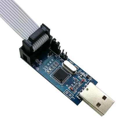
This page describes how to program the Next Generation Beacon units, i.e. VCO-PLL and DDS, using an alternative to Atmel Studio and an Atmel programmer. Instead the eXtreme Burner software and an USBasp programmer, available on eBay for less than 3 EUR, are used.
The USBasp programmer is available from eBay for less than 3 EUR.
Atmel USBasp programmer with 3,3 V/5 V target voltage jumper.
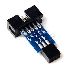
Because most of the USBasp programmers have a JTAG 10 pin connector you will also need a JTAG 10 pin to 6 pin adapter. They are also available from eBay typically for 1 EUR.
Atmel JTAG 10 pin to 6 pin adapter.
Please be aware that some USBasp programmers have the target voltage fixed at 3,3 V or 5 V. Some are fitted with a jumper that allows easy switching between the target voltages. Others have a couple of small solder pads where one must be open and the other one shorted to provide the correct target voltage. In any case when programming a Next Generation Beacons unit the programmer must be set for a target voltage of 3,3 V. Failure to do so may cause problems.
To program the relevant .hex file to the Atmel MCU the free eXtreme Burner is used.
Once eXtreme Burner is downloaded please unzip and execute the relevant installation program.
eXtreme Burner - AVR main screen.
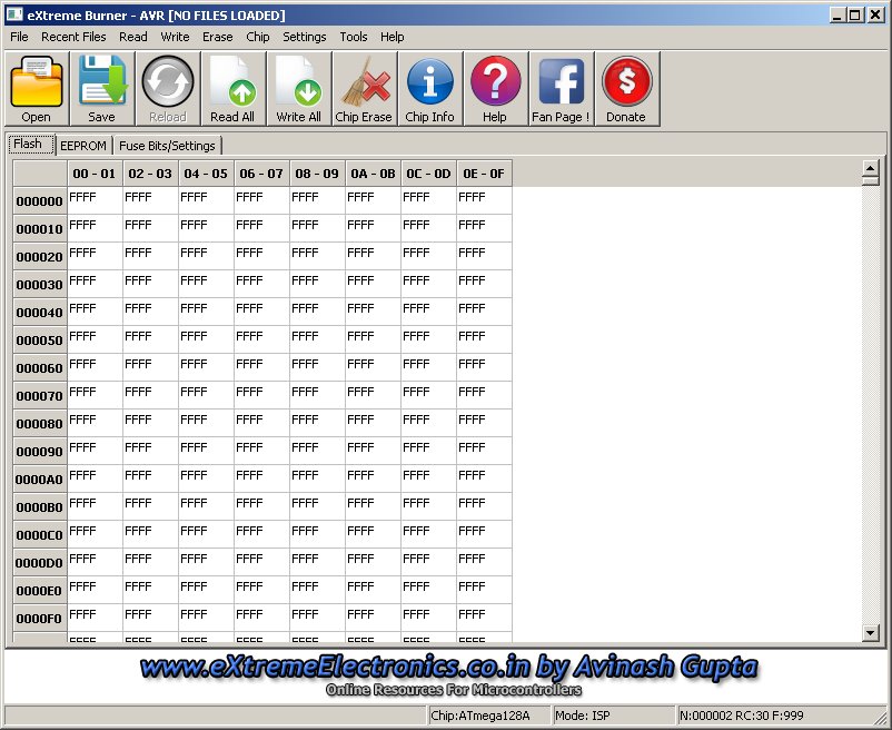
By default eXtreme Burner does not have the MCU data for the ATmega328 (VCO-PLL unit) and the ATmega128A (DDS unit). Therefore you will need to replace the existing chips.xml file with the one that is included in the extreme_burner.zip file. Chips.xml is located in the Data directory which is a subdirectory in the directory where you installed eXtreme Burner, typically C:\Program Files\eXtremeBurner\Data on a Windows PC. Alternatively you will have to edit the chips.xml file adding the data for the ATmega328 and ATmega128A.
ATmega328 data for the chips.xml file.
<CHIP>
   <NAME>ATmega328</NAME>
   <FLASH>32768</FLASH>
   <EEPROM>1024</EEPROM>
   <SIG>0x0014951E</SIG>
   <PAGE>64</PAGE>
   <LFUSE layout="2">YES</LFUSE>
   <HFUSE layout="5">YES</HFUSE>
   <EFUSE layout="4">YES</EFUSE>
   <LOCK>YES</LOCK>
   <CALIB>YES</CALIB>
   <PLACEMENT>.\Images\Placements\ZIF_DIP_40.bmp</PLACEMENT>
</CHIP>
ATmega328P data for the chips.xml file. The ATmega328P is used in the Arduino Uno and Arduino Nano.
<CHIP>
   <NAME>ATmega328P</NAME>
   <FLASH>32768</FLASH>
   <EEPROM>1024</EEPROM>
   <SIG>0x000F951E</SIG>
   <PAGE>64</PAGE>
   <LFUSE layout="2">YES</LFUSE>
   <HFUSE layout="5">YES</HFUSE>
   <EFUSE layout="4">YES</EFUSE>
   <LOCK>YES</LOCK>
   <CALIB>YES</CALIB>
   <PLACEMENT>.\Images\Placements\ZIF_DIP_40.bmp</PLACEMENT>
</CHIP>
ATmega128A data for the chips.xml file.
<CHIP>
   <NAME>ATmega128A</NAME>
   <FLASH>131072</FLASH>
   <EEPROM>4096</EEPROM>
   <SIG>0x0002971E</SIG>
   <PAGE>128</PAGE>
   <LFUSE layout="1">YES</LFUSE>
   <HFUSE layout="2">YES</HFUSE>
   <EFUSE layout="3">YES</EFUSE>
   <LOCK>YES</LOCK>
   <CALIB>YES</CALIB>
   <PLACEMENT>.\Images\Placements\ZIF_DIP_40.bmp</PLACEMENT>
</CHIP>
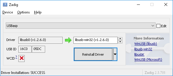
If eXtreme Burner says that it cannot find the libusb0.dll file please install, execute and use Zidag to install the driver.
The Zadig screen to load libusb0.dll driver.
Please ensure that the USBasp programmer is set for a 3,3 V target voltage.
Plug the USBasp programmer into the computer and connect it to the VCO-PLL using the JTAG to 6 pin adapter and apply voltage to the VCO-PLL unit.
Launch the eXtreme Burner program and select Menu | Chip | ATmega328.
This is only relevant if you have assembled the VCO-PLL unit yourself or want to change the "factory defaults." Select the Fuse Bits/Settings tabsheet and set/verify the fuses accordingly.
| Fuses | Hex value |
| Low Fuse | FF |
| High Fuse | D3 |
| Extended Fuse | FE |
| Lock Fuse | FF |
| Calibration | FFFFFFA0 |
If you want to write a new set of fuses check the relevant Write checkboxes and select Menu | Write | Fuse Bits and Lock Bits.
eXtreme Burner and the VCO-PLL fuse settings.

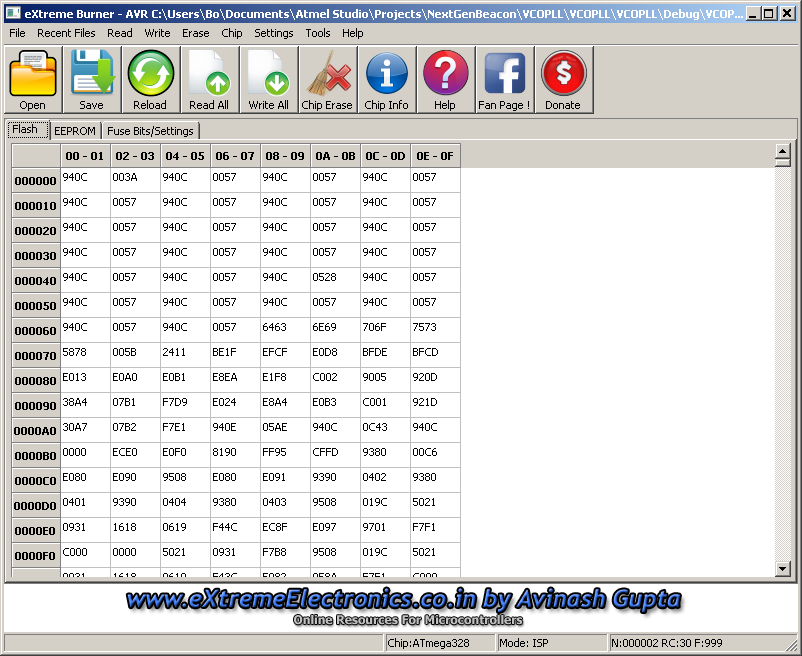
To program the VCOPLL.hex file to the VCO-PLL unit select the file from Menu | File | Open Flash then navigate to the file and select VCOPLL.hex and click the Open button. Then select Menu | Write | Flash.
After programming the new VCOPLL.hex file to the VCO-PLL unit it may be relevant to perform some configuration of the VCO-PLL unit. Please see the revision history for more details.
Please ensure that the USBasp programmer is set for a 3,3 V target voltage.
Plug the USBasp programmer into the computer and connect it to the DDS using the JTAG to 6 pin adapter and apply voltage to the DDS unit.
Launch the eXtreme Burner program and select Menu | Chip | ATmega128A.
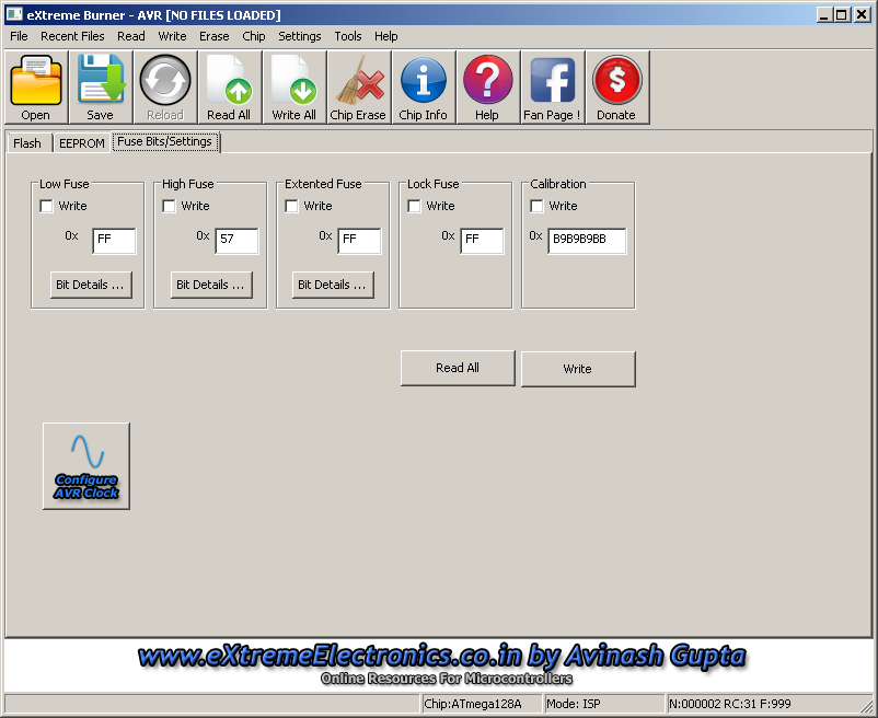
This is only relevant if you have assembled the DDS unit yourself or want to change the "factory defaults." Select the Fuse Bits/Settings tabsheet and set/verify the fuses accordingly.
| Fuses | Hex value |
| Low Fuse | FF |
| High Fuse | 57 |
| Extended Fuse | FF |
| Lock Fuse | FF |
| Calibration | B9B9B9BB |
If you want to write a new set of fuses check the relevant Write checkboxes and select Menu | Write | Fuse Bits and Lock Bits.
eXtreme Burner and the DDS fuse settings.
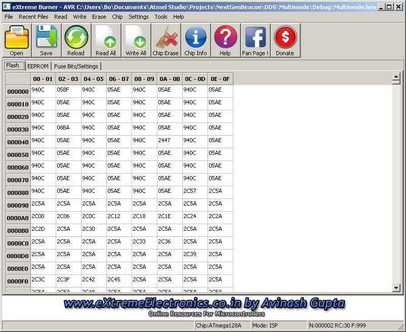
To program the Multimode.hex file to the DDS unit select the file from Menu | File | Open Flash then navigate to the file and select Multimode.hex and click the Open button. Then select Menu | Write | Flash.
After programming the new Multimode.hex file to the DDS unit it may be relevant to perform some configuration of the DDS unit. Please see the revision history for more details.
Bo, OZ2M, www.rudius.net/oz2m